


1–30
850 FEEDER PROTECTION SYSTEM – INSTRUCTION MANUAL
SPECIFICATIONS
CHAPTER 1: INTRODUCTION
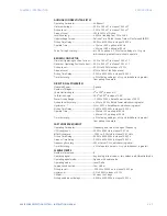
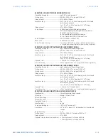
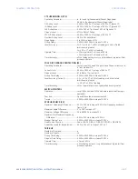
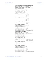
DATA LOGGER
Data Logger channels:.....................................16
Data Logger Rate: ..............................................1 cycle, 1 sec., 30 sec., 1 min., 15 min., 30 min., 1 hour
Inputs: ......................................................................Any analog parameter from the list of available analog
parameters
Data Collection Mode: ......................................Continuous, Triggered
Trigger Source:.....................................................Any digital flag from the list of digital flags
Trigger Position:...................................................0 to 50% in steps of 1%
Channel 1(16) Mode:..........................................Sample, Min, Max, Mean
EVENT RECORDER
Number of events:..............................................1024
Header:....................................................................relay name, order code, firmware revision
Content:...................................................................any element pickup, any element operate, digital input
change of state, digital output change of state, self-test
events
Data Storage:........................................................non-volatile memory
Time-tag Accuracy:...........................................to one microsecond
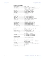
LAST TRIP DATA
Number of Records: ..........................................1
Data Storage:........................................................Non-volatile memory
Time-tag Accuracy:...........................................One microsecond
Actuals:....................................................................Event Number of Last Trip,
Timestamp of Last Trip,
Cause of Last Trip,
64 Configurable FlexAnalog values
Commands:...........................................................Clear Last Trip Data
User-Programmable Elements
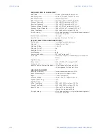
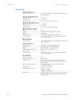
FLEXLOGIC
Lines of code:........................................................1024
Supported operations: .....................................NOT, XOR, OR (2 to 16 inputs), AND (2 to 16 inputs), NOR (2 to
16 inputs), NAND (2 to 16 inputs), latch (reset-dominant),
edge detectors, timers
Inputs: ......................................................................any logical variable, contact, or virtual input
Number of timers: .............................................. 32
Pickup delay: ........................................................0 to 60000 (ms, sec., min.) in steps of 1
Dropout delay:.....................................................0 to 60000 (ms, sec., min.) in steps of 1
Timer accuracy:.................................................. ±3% of delay setting or ±¼ cycle (whichever is greater) from
pickup to operate
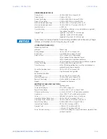
FLEXELEMENTS
Number of elements: ........................................8
Operating signal: ................................................Any analog actual value, or two values in a differential mode
Operating signal mode:...................................Signed, or Absolute value
Operating mode:.................................................Level, Delta
Comparison direction:......................................Over, Under
Pickup Level: .........................................................-30.000 to 30.000 pu in steps of 0.001 pu
Hysteresis: .............................................................0.1 to 50.0% in steps of 0.1%
Delta dt:...................................................................40 msec to 45 days
Pickup and dropout delays:...........................0.000 to 6000.000 s in steps of 0.001 s
FLEXSTATES
Number of States: ..............................................256 logical variables grouped under 16 Modbus addresses
Programmability:................................................Any FlexLogic operand, any digital input, any virtual input,
any remote input
Summary of Contents for Multilin 850
Page 10: ...VIII 850 FEEDER PROTECTION SYSTEM INSTRUCTION MANUAL ...
Page 135: ...CHAPTER 3 INTERFACES SOFTWARE INTERFACE 850 FEEDER PROTECTION SYSTEM INSTRUCTION MANUAL 3 41 ...
Page 151: ...CHAPTER 3 INTERFACES SOFTWARE INTERFACE 850 FEEDER PROTECTION SYSTEM INSTRUCTION MANUAL 3 57 ...
Page 153: ...CHAPTER 3 INTERFACES SOFTWARE INTERFACE 850 FEEDER PROTECTION SYSTEM INSTRUCTION MANUAL 3 59 ...
Page 439: ...CHAPTER 7 MONITORING FUNCTIONS 850 FEEDER PROTECTION SYSTEM INSTRUCTION MANUAL 7 19 ...
Page 644: ...11 20 850 FEEDER PROTECTION SYSTEM INSTRUCTION MANUAL FLEXELEMENTS CHAPTER 11 METERING ...