


CHAPTER 6: PROTECTION SETPOINTS
CURRENT ELEMENTS
850 FEEDER PROTECTION SYSTEM – INSTRUCTION MANUAL
6–73
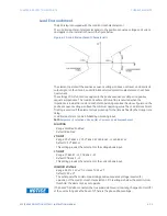
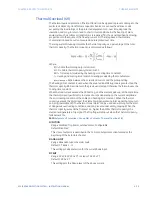
Load Encroachment
The 850 relay is equipped with the Load Encroachment element.
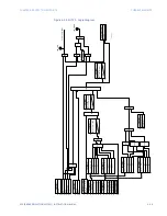
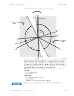
The Load Encroachment element responds to the positive-sequence voltage and current
and applies a characteristic shown in the figure below:
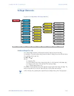
Figure 6-29: Load Encroachment Characteristic
The element operates if the positive-sequence voltage is above a set level, and asserts its
output signal so that it can be used to block selected protection elements such as Phase
Overcurrent.
The settings of this function are applied to the positive sequence voltage and positive
sequence impedance. The Load Encroachment Pickup flag is asserted when the
impedance is inside the Load Encroachment operating area (see the above figure) and the
positive sequence voltage is above the minimum operating value. The Load Encroachment
Trip flag is asserted if the element stays picked up for the time defined by the Pickup time
delay.
Load Encroachment can be inhibited by a blocking input.
Path
:
Setpoints > Protection > Group 1(6) > Current > Load Encroachment
FUNCTION
Range: Disabled, Enabled
Default: Disabled
VT INPUT
Range: Ph VT Bnk1-J2, Ph VT Bnk2-K2, LEA Bnk1 -J2, LEA Bnk2 -J2
Default: Ph VT Bnk1-J2
This setting provides the selection for the voltage bank input.
CT INPUT
Range: CT Bank 1 –J1, CT Bank 2 –K1
Default: CT Bank 1 -J1
This setting provides the selection for the current bank input.
MINIMUM VOLTAGE
Range: 0.00 to 1.50 x VT in steps of 0.01 x VT
Default: 0.20 x VT
The setting sets the minimum operating positive-sequence voltage required for
operation of the Load Encroachment element. If this voltage is below the set minimum
threshold, the element does not operate.
FASTPATH:
If 3-phase VT is delta connected, the true supervision level is internally changed to 1/sqrt(3)
of the user setting since the base of VT here is the phase-phase voltage.
Summary of Contents for Multilin 850
Page 10: ...VIII 850 FEEDER PROTECTION SYSTEM INSTRUCTION MANUAL ...
Page 135: ...CHAPTER 3 INTERFACES SOFTWARE INTERFACE 850 FEEDER PROTECTION SYSTEM INSTRUCTION MANUAL 3 41 ...
Page 151: ...CHAPTER 3 INTERFACES SOFTWARE INTERFACE 850 FEEDER PROTECTION SYSTEM INSTRUCTION MANUAL 3 57 ...
Page 153: ...CHAPTER 3 INTERFACES SOFTWARE INTERFACE 850 FEEDER PROTECTION SYSTEM INSTRUCTION MANUAL 3 59 ...
Page 439: ...CHAPTER 7 MONITORING FUNCTIONS 850 FEEDER PROTECTION SYSTEM INSTRUCTION MANUAL 7 19 ...
Page 644: ...11 20 850 FEEDER PROTECTION SYSTEM INSTRUCTION MANUAL FLEXELEMENTS CHAPTER 11 METERING ...