


CHAPTER 6: PROTECTION SETPOINTS
CURRENT ELEMENTS
850 FEEDER PROTECTION SYSTEM – INSTRUCTION MANUAL
6–57
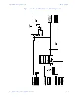
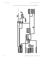
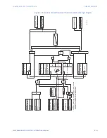
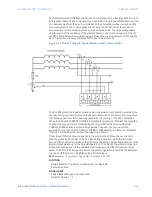
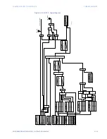
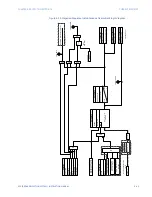
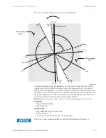
Switch on to Fault (SOTF)
Switch on to Fault protection (SOTF) is provided for high speed clearance of any detected
fault immediately following manual closure or closure after a long open time of the circuit
breaker. Without SOTF, there is a risk that if the breaker is closed onto close-in three-phase
fault, the measured voltages may be too small for the impedance zones or the directional
overcurrent stages to operate reliably.
NOTE
NOTE:
SOTF 1 (2 or 3) are associated with Breaker 1. The SOTF logic uses breaker status from
BKR1. SOTF 4 (5 or 6) are associated with Breaker 2. The SOTF logic uses breaker status
from BKR2. The CT Input and VT Input settings should be configured to match their
respective breakers.
Path
:
Setpoints > Protection > Group 1(6) > Current > SOTF 1(X)
FUNCTION
Range: Disabled, Trip, Alarm, Latched Alarm, Configurable
Default: Disabled
VT INPUT
Range: Ph VT Bnk1-J2
Default: Ph VT Bnk1-J2
CT INPUT
Range: CT Bank 1-J1
Default: CT Bank 1 -J1
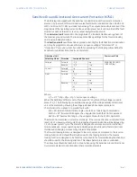
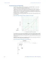
DEAD LINE MAX VOLTAGE
Range: 0.05 to 1.00 x VT in steps of 0.01
Default: 0.20 x VT
This setting sets the dead line voltage threshold. Voltage above this setting is not
considered for the dead line condition. To be in a dead line condition all phases must be
below this threshold.
DEAD LINE MAX CURRENT
Range: 0.05 to 1.00 x CT in steps of 0.01
Default: 0.05 x CT
This setting definesthe dead line current threshold. Currents above this setting value are
not considered to be in dead line condition. To be in dead line condition all phases have
to be below this threshold.
DEAD LINE PICKUP DELAY
Range: 0.000 to 6000.000 s in steps of 0.001
Default: 10.000 s
This setting defines the dead line pickup delay. Once in dead line condition for current
AND voltage, the dead line signal will be set after this delay if conditions are still true.
This value should be longer than the longest autoreclose shot time.
SOTF MAX VOLTAGE
Range: 0.05 to 3.00 x VT in steps of 0.01
Default: 0.50 x VT
This setting defines the SOTF maximum voltage threshold. Above this setting the
element is not in SOTF condition. To be in SOTF condition, the same phase for current
and voltage have to be in SOTF condition.
FASTPATH:
VTs should be connected to the line side and not the bus side for detection by voltage and
currents.
Summary of Contents for Multilin 850
Page 10: ...VIII 850 FEEDER PROTECTION SYSTEM INSTRUCTION MANUAL ...
Page 135: ...CHAPTER 3 INTERFACES SOFTWARE INTERFACE 850 FEEDER PROTECTION SYSTEM INSTRUCTION MANUAL 3 41 ...
Page 151: ...CHAPTER 3 INTERFACES SOFTWARE INTERFACE 850 FEEDER PROTECTION SYSTEM INSTRUCTION MANUAL 3 57 ...
Page 153: ...CHAPTER 3 INTERFACES SOFTWARE INTERFACE 850 FEEDER PROTECTION SYSTEM INSTRUCTION MANUAL 3 59 ...
Page 439: ...CHAPTER 7 MONITORING FUNCTIONS 850 FEEDER PROTECTION SYSTEM INSTRUCTION MANUAL 7 19 ...
Page 644: ...11 20 850 FEEDER PROTECTION SYSTEM INSTRUCTION MANUAL FLEXELEMENTS CHAPTER 11 METERING ...