


CHAPTER 6: PROTECTION SETPOINTS
CURRENT ELEMENTS
850 FEEDER PROTECTION SYSTEM – INSTRUCTION MANUAL
6–17
Phase Directional Overcurrent Protection (67P)
The 850 Phase Directional Overcurrent protection elements (one for each of phases A, B,
and C) determine the phase current flow direction for steady state and fault conditions and
can be used to control the operation of the phase overcurrent elements by sending
directional bits to inputs of these elements.
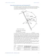
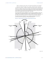
The element is intended to send a directional signal to an overcurrent element to prevent
an operation when current is flowing in a particular direction. The direction of current flow
is determined by measuring the phase angle between the current from the phase CTs and
the line-line voltage from the VTs, based on the 90° or quadrature connection. To increase
security for three phase faults very close to the VTs used to measure the polarizing voltage,
a voltage memory feature is incorporated. This feature remembers the measurement of
the polarizing voltage 3 cycles back - from the moment the voltage collapsed below the
“polarizing voltage threshold” - and uses it to determine direction. The voltage memory
remains valid for one second after the voltage has collapsed.
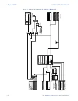
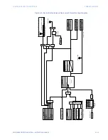
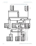
The main component of the phase directional element is the phase angle comparator with
two inputs: the operating signal (phase current) and the polarizing signal (the line voltage,
shifted in the leading direction by the characteristic angle, ECA).
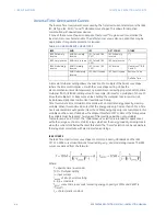
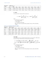
The following table shows the operating and polarizing signals used for phase directional
control:
PHASE
OPERATING SIGNAL
POLARIZING SIGNAL (Vpol)
ABC PHASE SEQUENCE
ACB PHASE SEQUENCE
A
Angle of Ia
Angle of Vbc × (1
∠
ECA)
Angle of Vcb × (1
∠
ECA)
B
Angle of Ib
Angle of Vca × (1
∠
ECA)
Angle of Vac × (1
∠
ECA)
C
Angle of Ic
Angle of Vab × (1
∠
ECA)
Angle of Vba × (1
∠
ECA)
Summary of Contents for Multilin 850
Page 10: ...VIII 850 FEEDER PROTECTION SYSTEM INSTRUCTION MANUAL ...
Page 135: ...CHAPTER 3 INTERFACES SOFTWARE INTERFACE 850 FEEDER PROTECTION SYSTEM INSTRUCTION MANUAL 3 41 ...
Page 151: ...CHAPTER 3 INTERFACES SOFTWARE INTERFACE 850 FEEDER PROTECTION SYSTEM INSTRUCTION MANUAL 3 57 ...
Page 153: ...CHAPTER 3 INTERFACES SOFTWARE INTERFACE 850 FEEDER PROTECTION SYSTEM INSTRUCTION MANUAL 3 59 ...
Page 439: ...CHAPTER 7 MONITORING FUNCTIONS 850 FEEDER PROTECTION SYSTEM INSTRUCTION MANUAL 7 19 ...
Page 644: ...11 20 850 FEEDER PROTECTION SYSTEM INSTRUCTION MANUAL FLEXELEMENTS CHAPTER 11 METERING ...