


6–4
850 FEEDER PROTECTION SYSTEM – INSTRUCTION MANUAL
CURRENT ELEMENTS
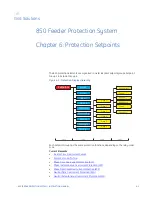
CHAPTER 6: PROTECTION SETPOINTS
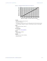
Inverse Time Overcurrent Curves
The Inverse Time Overcurrent Curves used by the Time Overcurrent elements are the IEEE,
IEC, GE Type IAC, ANSI, I
2
t and I
4
t standard curve shapes. This allows for simplified
coordination with downstream devices.
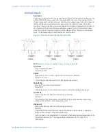
If none of these curve shapes is adequate, FlexCurves™ may be used to customize the
inverse time curve characteristics. The definite time curve is also an option that may be
appropriate if only simple protection is required.
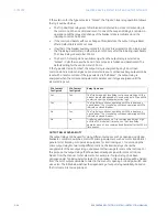
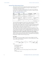
Table 6-1: OVERCURRENT CURVE TYPES
A time dial multiplier setting allows the selection of a multiple of the base curve shape
(where the time dial multiplier = 1) with the curve shape setting. Unlike the
electromechanical time dial equivalent, operate times are directly proportional to the time
multiplier (TD MULTIPLIER) setting value. For example, all times for a multiplier of 10 are 10
times the multiplier 1 or base curve values. Setting the multiplier to zero results in an
instantaneous response to all current levels above Pickup.
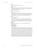
Time Overcurrent time calculations are made with an internal
energy capacity
memory
variable. When this variable indicates that the energy capacity has reached 100%, a Time
Overcurrent element will operate. If less than 100% energy capacity is accumulated in this
variable and the current falls below the dropout threshold of 97 to 98% of the Pickup value,
the variable must be reduced. Two types of this resetting operation are available:
“Instantaneous” and “Timed”. The “Instantaneous” selection is intended for applications
with other relays, such as most static relays, which set the energy capacity directly to zero
when the current falls below the reset threshold. The “Timed” selection can be used where
the relay must coordinate with electromechanical relays.
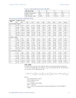
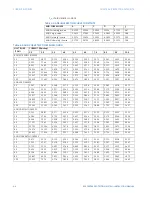
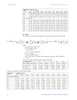
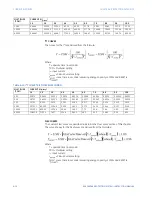
IEEE CURVES
The IEEE Time Overcurrent curve shapes conform to industry standards and the IEEE
C37.112-1996 curve classifications for extremely, very, and moderately inverse. The IEEE
curves are derived from the formula:
Where:
T = operate time (in seconds)
TDM = Multiplier setting
I = input current
I
pickup
= Pickup Current setting
A, B, p = constants
T
RESET
= reset time in seconds (assuming energy capacity is 100% and RESET is
“Timed”)
t
r
= characteristic constant
IEEE
ANSI
IEC
GE TYPE IAC
OTHER
IEEE Extremely
Inverse
ANSI Extremely
Inverse
IEC Curve A (BS
142)
IAC Extremely
Inverse
I
2
t
IEEE Very Inverse
ANSI Very Inverse IEC Curve B (BS
142)
IAC Very Inverse
I
4
t
IEEE Moderately
Inverse
ANSI Normally
Inverse
IEC Curve C (BS
142)
IAC Inverse
FlexCurves™ A, B,
C and D
ANSI Moderately
Inverse
IEC Short Inverse
IAC Short Inverse
Recloser Curve
Definite Time
Summary of Contents for Multilin 850
Page 10: ...VIII 850 FEEDER PROTECTION SYSTEM INSTRUCTION MANUAL ...
Page 135: ...CHAPTER 3 INTERFACES SOFTWARE INTERFACE 850 FEEDER PROTECTION SYSTEM INSTRUCTION MANUAL 3 41 ...
Page 151: ...CHAPTER 3 INTERFACES SOFTWARE INTERFACE 850 FEEDER PROTECTION SYSTEM INSTRUCTION MANUAL 3 57 ...
Page 153: ...CHAPTER 3 INTERFACES SOFTWARE INTERFACE 850 FEEDER PROTECTION SYSTEM INSTRUCTION MANUAL 3 59 ...
Page 439: ...CHAPTER 7 MONITORING FUNCTIONS 850 FEEDER PROTECTION SYSTEM INSTRUCTION MANUAL 7 19 ...
Page 644: ...11 20 850 FEEDER PROTECTION SYSTEM INSTRUCTION MANUAL FLEXELEMENTS CHAPTER 11 METERING ...