


CHAPTER 5: DEVICE, SYSTEM, INPUT AND OUTPUT SETPOINTS
OUTPUTS
850 FEEDER PROTECTION SYSTEM – INSTRUCTION MANUAL
5–105
Analog Outputs
Description
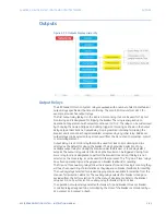
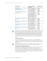
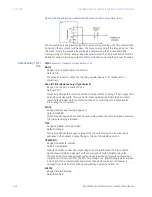
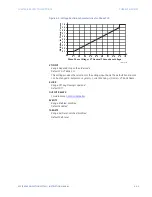
Depending on the order code, the 8 Series relay supports one optional DC analog card. The
Analog card has 4 analog inputs and 7 analog outputs. There are three Analog Output
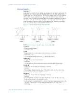
channel scenarios for analog minimum and maximum output range: A, B, and C shown in
the figure below. Type A characteristics apply when the minimum range is 0 and the
maximum range is a positive (+ve) value. Type B characteristics apply when the minimum
and maximum ranges are definitely positive (+ve) values. Type C characteristics apply
when the minimum range is a negative (-ve) and the maximum range is a positive (+ve)
value. The following diagram illustrates these characteristics.
Figure 5-39: Analog Outputs Channel Characteristics
Path
:
Setpoints > Outputs > Analog Outputs > Analog Output 1(X)
FUNCTION
Range: Disabled, Enabled
Default: Disabled
RANGE
Range: 0 to 1 mA, 0 to 5 mA, 0 to 10 mA, 0 to 20 mA, or 4 to 20 mA
Default: 0 to 1 mA
This setting provides the selection for the analog output range.
PARAMETER
Range: Off, any Flex Analog Parameter
Default: Off
This setting selects the measured parameter to control the Analog Output level.
MIN VALUE
Range: Populates per selection of the analog parameter
Default: 0
This setting defines the minimum value of the analog output quantity. It populates
based on the selection of the analog parameter.
MAX VALUE
Range: Populates per selection of the analog parameter
Default: 0
This setting defines the maximum value of the analog output quantity. It populates
based on the selection of the analog parameter.
Each channel can be programmed to represent a FlexAnalog parameter available in the
respective 8 Series relay. The range and steps is the same as the range of the
FlexAnalog.
Summary of Contents for Multilin 850
Page 10: ...VIII 850 FEEDER PROTECTION SYSTEM INSTRUCTION MANUAL ...
Page 135: ...CHAPTER 3 INTERFACES SOFTWARE INTERFACE 850 FEEDER PROTECTION SYSTEM INSTRUCTION MANUAL 3 41 ...
Page 151: ...CHAPTER 3 INTERFACES SOFTWARE INTERFACE 850 FEEDER PROTECTION SYSTEM INSTRUCTION MANUAL 3 57 ...
Page 153: ...CHAPTER 3 INTERFACES SOFTWARE INTERFACE 850 FEEDER PROTECTION SYSTEM INSTRUCTION MANUAL 3 59 ...
Page 439: ...CHAPTER 7 MONITORING FUNCTIONS 850 FEEDER PROTECTION SYSTEM INSTRUCTION MANUAL 7 19 ...
Page 644: ...11 20 850 FEEDER PROTECTION SYSTEM INSTRUCTION MANUAL FLEXELEMENTS CHAPTER 11 METERING ...