


A–6
489 GENERATOR MANAGEMENT RELAY – INSTRUCTION MANUAL
CHAPTER A: APPENDIX
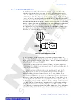
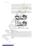
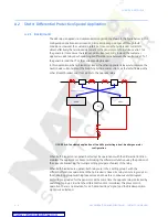
Applications with generators operated in parallel and grounded through a common
impedance require special considerations. If only one generator is grounded and the other
ones left floating, the directional element for the floating generators does not receive a
correct
V
neutral
signal and therefore cannot operate correctly. In those applications, the
element makes use of auxiliary contacts off the grounding switch and the unit breaker to
turn the element into a simple overcurrent element, with the pickup level set for the
directional element (note that the ground directional element and the ground overcurrent
elements are totally separate elements). In this mode, the element can retain a high
sensitivity and fast operate time since it will only respond to internal stator ground faults.
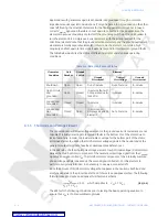
The table below illustrates the status of different elements under various operating
conditions.
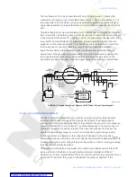
A.1.5 Third Harmonic Voltage Element
The conventional neutral overvoltage element or the ground overcurrent element are not
capable of reliably detecting stator ground faults in the bottom 5% of the stator, due to
lack of sensitivity. In order to provide reliable coverage for the bottom part of the stator,
protective elements, utilizing the third harmonic voltage signals in the neutral and at the
generator output terminals, have been developed (see Reference 4).
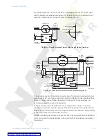
In the 489 relay, the third-harmonic voltage element, Neutral Undervoltage (3rd Harmonic)
derives the third harmonic component of the neutral-point voltage signal from the
V
neutral
signal as one signal, called
V
N
3
. The third harmonic component of the internally summed
phase-voltage signals is derived as the second signal, called
V
P
3
. For this element to
perform as originally intended, it is necessary to use wye-connected VTs.
Since the amount of third harmonic voltage that appears in the neutral is both load and
machine dependent, the protection method of choice is an adaptive method. The following
formula is used to create an adaptive third-harmonic scheme:
(EQ 1.1)
The 489 tests the following conditions prior to testing the basic operating equation to
ensure that
V
N
3
is of a measurable magnitude:
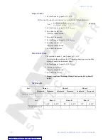
Table A–1: Detection Element Status
Generator
Condition
Unit
Breaker
Ground
Switch
Element
Ground
Directional
Neutral
Overvoltage
Ground
Overcurrent
Shutdown
Open
Open
Out-of-service
Out-of-service
In-service
Open Circuit
and
grounded
Open
Closed
In-service (but will
not operate due to
lack of I
0
)
In-service
In-service
Loaded and
Grounded
Closed
Closed
In-service
In-service
In-service
Loaded and
Not
Grounded
Closed
Open
In service as a
simple overcurrent
element
Out-of-service
In-service
V
N
3
V
P
3
3
⁄
V
N
3
+
-------------------------------
0.15 which simplifies to
V
P
3
17
V
N
3
≥
≤


