


CHAPTER 7: TESTING
489 GENERATOR MANAGEMENT RELAY – INSTRUCTION MANUAL
7–5
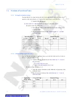
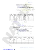
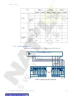
7.2.3
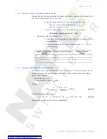
Ground (1 A), Neutral, and Differential Current Accuracy
The specification for neutral, differential and 1 A ground current input accuracy is
±
0.5% of
2
×
CT. Perform the steps below to verify accuracy.
Z
In the
S2 SYSTEM SETUP
Z
CURRENT SENSING
menu, set:
GROUND CT:
“1A Secondary”
GROUND CT RATIO:
“1000:1”
PHASE CT PRIMARY:
“1000 A”
Z
In the
S5 CURRENT ELEMENTS
ZV
PHASE DIFFERENTIAL
menu, set:
PHASE DIFFERENTIAL TRIP:
“Unlatched”
DIFFERENTIAL TRIP MIN. PICKUP:
“0.1 x CT”
The last two setpoints are needed to view the neutral and the differential current.
The trip element will operate when differential current exceeds 100 A.
Measured values should be
±
10 A.
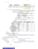
Z
Inject (
I
A
only) the values shown in the table below into one phase only
and verify accuracy of the measured values.
Z
View the measured values in the
A2 METERING DATA
Z
CURRENT
METERING
menu or press the
NEXT
key to view the current values when
differential trip element is active.
200 V
2000 V
Applied Line-
Neutral Voltage
Expected Voltage
Reading
Measured Voltage
A-N
B-N
C-N
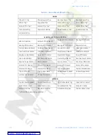
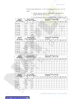
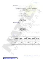
Table 7–1: Neutral and Ground Current Test Results
Injected
Current
1 A Unit
Expected
Current
Measured
Ground Current
Measured Neutral Current
Phase A
Phase B
Phase C
0.1 A
100 A
0.2 A
200 A
0.5 A
500 A
1 A
1000 A
Table 7–2: Differential Current Test Results
Injected
Current
Expected Current Reading
Measured Differential Current
Differential
Phase A
Differential
Phase B,C
Phase A
Phase B
Phase C
0.1 A
200 A
100 A
0.2 A
400 A
200 A
0.5 A
1000 A
500 A
1 A
2000 A
1000 A


