background image

– 42 –

Surface Burner Valve and Switch 

Each surface burner valve utilizes a switch. When a 
burner knob is turned to the ON position, the valve 
switch closes and activates the spark module and 
the LED light. Each surface burner valve switch is 
installed on the front of the burner valve body. The 
switches are all wired to a single harness and are 
replaced as one assembly. It is necessary to remove 
the valve to access the switch.

Note:

 The following describes the procedure to 

remove a single burner valve and switch. The 
procedure to remove the remaining valves and 
switches is identical. 

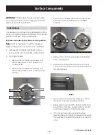
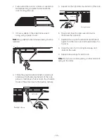
To remove the surface burner valve and switch:

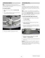
Remove the burner pan located over the valve 

1. 

and switch to be replaced. (See 

Surface Burner 

Pan

.)

Remove the heat barrier by lifting it out of the 

2. 

burner box.

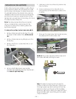
Remove the 7/16-in. nut and the 9/16-in. nut 

3. 

from the valve.

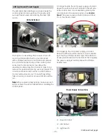
4.  Remove the Phillips-head screw and the 

indicator light assembly from the valve bracket. 
(See 

Indicator Light Assembly

.)

5.  Slide down and remove the wiring retainer clip 

from the frame.

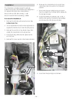
6.  Using a ratchet wrench, remove the 1/4-in. 

hex-head screw that attaches the valve to the 
manifold.

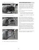
7.  Maneuver the valve below the bracket and slide 

the valve switch from the valve stem.

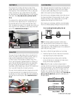
Caution:

 Ensure the valve seal and the screw seal 

are in place BEFORE installing the valve.

Screw Seal

Valve Seal

Clip

Valve Switch

Valve Stem

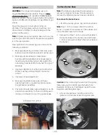
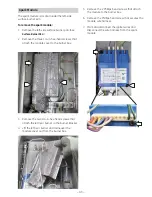
Note:

 The bottom of each switch is molded to 

conform to the front of the valve for a locked-in 

fi

 t. 

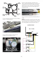
For proper igniter operation, each switch must be 
locked-in to the top of the valve. When installing 
the switch, align each switch to the valve stem and 
body. Push the switch down 

fi

 rmly until an audible 

"snap" is detected.

Summary of Contents for Monogram ZDP486ND

Page 1: ...sville Kentucky 40225 31 9181 Monogram Professional Range and Rangetops ZDP486ND ZDP486NR ZDP484NG ZDP364ND ZDP364NR ZDP366N ZDP304N Technical Service Guide June 2009 GE Consumer Industrial ZGU366N ZG...

Page 2: ...witch do not use any phone in the building Immediately call the gas supplier from a neighbor s phone Follow the gas supplier s instructions If you cannot reach the gas supplier call the fire departmen...

Page 3: ...agnostics and Service Information 71 Door Assembly 51 Electronic Oven Control 67 Factory Test Mode 71 Gas Conversion Range and Rangetop 22 Glow bar Igniter 39 Griddle Assembly 35 Griddle Burner Ignite...

Page 4: ...Relay Board 60 Oven Sensor Sail and Door Switch Test 76 Oven TCO 49 Oven Temperature Sensor 56 Range Components 47 Sail Switch 49 Schematics and Wiring Diagrams 77 Side Access Panel 47 Spark Module 4...

Page 5: ...her to accommodate round bottom woks Stainless steel and aluminum clad griddle offers 18 000 BTUs of cooking power allowing fast and consistent heating across the entire cooking surface Grill with inf...

Page 6: ...ill None All Burner Model Model Year Designator Z D P 4 8 6 N D P S S Nomenclature Range Nomenclature Model Number Fuel Type N Natural Gas L Liquid Propane The mini manual is located at the bottom beh...

Page 7: ...Grill Model Year Designator Z G U 4 8 6 N D P S S Nomenclature Rangetop Nomenclature Model Number Fuel Type N Natural Gas L Liquid Propane The mini manual is located on the bottom next to the gas inle...

Page 8: ...ezel 9 7 8 6 1 4 3 ZGU486NR ZGU486LR 6 burners and grill ZGU486ND ZGU486LD 6 burners and griddle ZGU484NG ZGU484LG 4 burners grill and griddle ZGU364NR ZGU364LR 4 burners and grill ZGU364ND ZGU364LD 4...

Page 9: ...wise to the LITE position Simmering The stacked burner design provides a wide range of heat settings with which to simmer Depending on the type and quantity of food and pan size the flame can be adjus...

Page 10: ...o the grill once the Glo Bar reaches temperature Using the Griddle The griddle is thermostatically controlled and can be set to maintain any temperature from 200 F to 450 F Note Unlike the surface bur...

Page 11: ...7 8 6 15 14 12 13 17 1 4 10 3 ZDP486NR ZDP486LR 6 burners and grill ZDP486ND ZDP486LD 6 burners and griddle ZDP484NG ZDP484LG 4 burners grill and griddle ZDP364NR ZDP364LR 4 burners and grill ZDP364N...

Page 12: ...e self clean temperature is automatically set 1 Mini Knob Turn to select and push to enter PROBE or TIMER settings Also to adjust CLEAN cycle time 2 Timer Button Push to select the kitchen timer funct...

Page 13: ...t the display will show the actual temperature The interior lights will turn on and stay on until the oven is turned off The convection oven fan will turn on temporarily during preheat The control wil...

Page 14: ...ned off The convection fan will turn on when CONV BROIL is selected 3 When broiling is finished turn the Oven Mode Selector and the Temperature knob to OFF Note Broil will not work if the temperature...

Page 15: ...Inner Introduction to Convection Cooking The Monogram reverse air convection system consists of two dedicated heating elements wrapped around the convection fan After preheating to the set temperatur...

Page 16: ...the Oven Mode Selector to OFF Mini Knob Turn to adjust Push to select The symbol will flash as the oven door is locked It will not be possible to open the oven door during the clean cycle 4 After the...

Page 17: ...he one it replaced Use your new oven for a few weeks to become more familiar with it If you still think your new oven is too hot or too cold you can adjust the thermostat yourself On double oven model...

Page 18: ...cial Features Mini Knob Turn to adjust Push to select 2 Turn the Mini Knob clockwise until the display scrolls SAbbAtH Push the Mini Knob to select the Sabbath mode 3 Once SAbbAtH is selected the disp...

Page 19: ...0 volt 60 Hz and connected to an individual properly grounded branch circuit This branch circuit is to be protected by a circuit breaker or time delay fuse 50 amp for 48 ranges 30 amp for 36 and 30 ra...

Page 20: ...NOT INSTALL THE RANGE LOWER THAN ADJACENT COUNTERTOP HEIGHT The range must be supported by all 4 legs regardless of countertop height Front leg adjustment Note If toe kick is installed pull to remove...

Page 21: ...isk of tipping the range the range must be secured by a properly installed anti tip bracket See installation instructions shipped with the bracket for complete details before attempting to install To...

Page 22: ...CE HOLDER The range orifice holder is located behind the front access panel at the bottom of the range The rangetop orifice holder is located inside the range insulation cover Additional orifices may...

Page 23: ...fices using a 7 mm nut driver Use small pliers to carefully lift out the orifices The main orifice is located low in the center of the burner while the simmer orifice is located higher beside the cent...

Page 24: ...Griddle orifice Select for your gas type LP 047 NAT 076 A Lift off the griddle flue cover Remove the 2 inside clamping screws B Use a pad or piece of carton to protect the adjacent surface Slide the...

Page 25: ...of No Bake Yes Convection Bake Yes Convection Roast Yes Convection Broil No Std Broil No Clean No Sabbath Mode No Probe Usage Yes ADJUST BURNER FLAMES Normally burnersdonotneedfurtheradjustment Makead...

Page 26: ...the oven during a broil cycle The Clean cycle can be set for a minimum of 3 hours and a maximum of 5 hours The default setting is 5 hours The 5 hour set time consists of 4 hours and 15 minutes of clea...

Page 27: ...Front of Range 48 in range shown Continued next page Lights Lights Lights Convection Fan Convection Fan Oven Door Gasket Broil Element Broil Element Rangetop Task Light Switch Control Panel Oven Door...

Page 28: ...ection Fan Convection Fan Convection Element Convection Element Broil Element Broil Element Cooling Fan Cooling Fan Shutoff Valve Regulator Level Leg Extension Rod Level Leg Extension Rod Gas Inlet Pi...

Page 29: ...ntrol Griddle Burner Griddle Burner Igniter Grill Burner Grill Burner Igniter Burner Rangetop ZGU484NG burner pans top heat barriers grill and griddle removed Griddle IR Infrared Grill LED Task Lighti...

Page 30: ...he Phillips head screw at each front corner that attaches the front of the side trim to the control panel 3 Remove the 2 Phillips head screws within each bezel that attach the bezel to the manifold br...

Page 31: ...embly Note The following describes the procedure to remove the grill assembly To remove the grill Lift off the grill grate and grill frame 1 Lift the grill baffle straight up and remove it from 2 the...

Page 32: ...pplicable 11 Remove the 2 Phillips head screws from the front and the 2 Phillips head screws from the rear of the grill burner box Front of Grill Burner Box Rear of Grill Burner Box 6 Remove the two 1...

Page 33: ...box 3 Pull the harness connector thru the cutout and disconnect the igniter wire harness Spring Clip Grill Safety Valve Note The following describes the procedure to remove the grill safety valve The...

Page 34: ...tabs away from 2 the switches and remove the switches from the switch bracket Mark and disconnect the wires from the 2 3 switches Tab Tab To remove the grill control Remove the grill control switches...

Page 35: ...is attached with 2 Phillips head screws 3 Push the griddle toward the back of the range to release tabs from slots on the front of the range Tab Front of Range Slot Caution The griddle is heavy Use ca...

Page 36: ...the two 1 4 in hex head igniter screws 9 Remove the grease trough 10 Remove the 4 Phillips head screws that attach the rear trim 11 Place the control panel in the service position See Control Panel 12...

Page 37: ...1 of 2 Heat Barrier Griddle Control The control utilizes a capillary that senses griddle temperature and a switch that operates the LED indicator light When the griddle knob is turned to the ON positi...

Page 38: ...ITER SURFACE TEMPERATURE INCREASES THE SAFETY VALVE OPERATES BY CURRENT NOT VOLTAGE From a cold start the igniter needs 30 to 60 seconds with a minimum of 116 volts applied to reduce its electrical re...

Page 39: ...Orifice must be pointing straight into burner venturi Improper air gas adjustment 4 Blockage of griddle burner gas exit holes 5 Internal restriction or partial restriction inside the grill burner asse...

Page 40: ...ove 4 the Phillips screws on the front of the oven vent then pull the vent toward the front to release a tab at each end 5 Remove the adjacent grill griddle See Grill Assembly or Griddle Assembly 6 Re...

Page 41: ...acent grill griddle burner box See Grill Assembly or Griddle Assembly Use extreme care when removing or installing the burner pan 6 Lift and tilt the side opposite the adjacent grill griddle and slide...

Page 42: ...heat barrier by lifting it out of the 2 burner box Remove the 7 16 in nut and the 9 16 in nut 3 from the valve 4 Remove the Phillips head screw and the indicator light assembly from the valve bracket...

Page 43: ...cover to the burner box 3 Remove the two 1 4 in hex head screws that attach the left rear burner to the burner bracket 4 Lift the left rear burner and maneuver the module cover out from the burner box...

Page 44: ...two 1 4 in hex head screws that 3 attach the transformer to the burner box Disconnect the surface burner igniter switch 4 wire harness Remove the top screw from the harness bracket 5 Transformer Disco...

Page 45: ...bly fails or a wiring connection is loose all LEDs will be out Note When replacing task lighting make sure each light is centered over each bezel before installing the control panel LEDs Activated Con...

Page 46: ...ator light assembly Place the control panel in the service position 1 See Control Panel Disconnect the LED wire harness 2 Remove the Phillips head screw that attaches 3 the LED to the valve bracket Di...

Page 47: ...2 See Control Panel Remove the three 1 4 in hex head screws that 3 attach the side panel to the rear of the range Back Panel The back panel is attached with seventeen 1 4 in hex head screws It is nec...

Page 48: ...oking modes the fan always runs in low speed It will only run in high speed in the unlikely event the oven exceeds 600 F in a cooking mode Main oven fan characteristics High speed 3050 RPM 100 Resista...

Page 49: ...ck Assembly The motorized door lock assembly is located above the oven The assembly consists of a lock motor cam and switch assembly lock hook mounting plate door switch spring and plunger The lock mo...

Page 50: ...incorrectly to the lock assembly When reconnecting the wiring make sure it is properly connected to the lock assembly before turning the power back on If the lock motor fails during a self clean cycle...

Page 51: ...oor assembly from the outer door assembly To replace the outer door assembly Separate the door assemblies See 1 To separate the door assemblies this section Remove the 3 8 in hex head screw that 2 att...

Page 52: ...gasket forms a complete seal around the front edge of the oven liner and the inner door panel The door gasket is attached to the inner door panel by spring clips When removing the gasket pull the ends...

Page 53: ...53 Oven Doors exploded view Main Oven Door Companion Oven Door...

Page 54: ...the rear rack supports and press the front rack locks onto the front rack supports 3 Pull the rack all the way out to check that it is properly engaged Lift to unlock front rack locks from the rack su...

Page 55: ...slide mechanism of the rack 5 2 Fully extend the rack on a table or countertop Newspaper may be placed underneath the rack for easy clean up Open and close the rack several times to 6 distribute the l...

Page 56: ...start broil again The broil element is composed of an inner and an outer element It is replaced as one unit The broil element will not work if the temperature probe is plugged in The main oven inside...

Page 57: ...62 and draws approximately 3 4 amps The main oven outside element is rated at 1600 watts has an approximate resistance value of 35 and draws approximately 6 3 amps The companion oven inside element is...

Page 58: ...n fan assembly can be removed from inside the oven The convection fan operates during the following modes Preheat Convection Bake Convection Broil Convection Roast Preheat the fan will start after a 1...

Page 59: ...emblies Remove the four 1 4 in hex head screws that 2 hold the convection cover to the back wall of the oven cavity Remove the outer six 1 4 in hex head screws 3 that attach the fan assembly to the ba...

Page 60: ...oard to the control panel then carefully lift the assembly from the control panel Screw Locations for Double Oven Models Bottom View of Range Service Position Oven Relay Board The oven relay board is...

Page 61: ...a bake element Remove the oven door 1 See Door Assembly Lower the relay board access panel to provide 2 needed clearance See Oven Relay Board If necessary extend the right front leveling leg 3 down to...

Page 62: ...ate 10 Carefully remove the front center insulation piece Note Upon reassembly ensure displaced insulation around oven and components is returned to its original position Tab Center Front Insulation C...

Page 63: ...rd in the control compartment with the harness The meat probe has a resistance value of 30K 50K at room temperature To remove the meat probe receptacle Separate the light housing from the oven liner 1...

Page 64: ...installation 1 Remove the back panel See 2 Back Panel Disconnect the meat probe outlet wire harness 3 Disconnect Side Access Panel Retrieval Wire 5 Remove the meat probe receptacle See To remove the...

Page 65: ...dels follow procedure A To remove the light assemblies from the left side of the main oven and the right side of the companion oven on 48 in models follow procedure B Procedure A Remove the range from...

Page 66: ...oven is in a cooking cycle Each light assembly consists of a removable light cover with two locking clips and a light compartment with three halogen bulbs Be sure to let the light cover and bulb cool...

Page 67: ...ach oven that can operate in any combination There can be several minutes of off time between bake and broil unit operation after preheat ELEMENTS FANS Conv Conv Cooling Cooling Oven Latch Mode Bake 1...

Page 68: ...erature encoders and relay boards are the LIN slaves The logic board sends messages to the other components based on a predefined list of commands All the components receive a signal to perform a spec...

Page 69: ...Broil Element 1 K4 Convection Fan On Off K5 Convection Element 2 K7 Bake Element 1 K8 Bake Element 2 K10 Convection Element 1 K11 Broil Element 2 K13 Door Lock K14 DLB Double Line Break Daughter Rela...

Page 70: ...MAIN OVEN RELAY BOARD J2 J1 K2 K12 K1 AS VIEWED FROM FRONT OF RANGE 9 1 5 1 3 1 5 J5 R R R CW OW 1 6 J7 1 J14 K1 K4 K5 K8 K11 K3 K7 K10 K14 K13 J16 G O R S Y RW S B C W V R J11 J17 1 W B Y S P S O N...

Page 71: ...y other selections are made Press and hold the PUSH TO SELECT knob for approximately 3 seconds within the first 2 minutes The display will show Prod The options for Factory Test are cycled through by...

Page 72: ...ht If Single Oven 23a 35 seconds Sound System Beep If Double Oven 23b 35 seconds Turn on Bake Element 1 24 37 seconds Turn off Bake Element 1 and wait 25 38 seconds Turn on Bake Element 2 26 40 second...

Page 73: ...d press displays Probe temperature 4th press displays oven temperature 5th press displays all red LED segments 6th press displays all green LED segments 7th press displays EEPROM programming 8th press...

Page 74: ...pen sail switch Suspect stalled cooling fan or airflow to control area CX C1 C4 Communication Error Check harness first and then replace component indicated by Cx Error Code FC Door Latch Error Inspec...

Page 75: ...ol will beep continuously and scroll Bad LinE across available displays main and companion oven if applicable L1 L2 L1 N Status 240VAC Voltage present Normal 240 VAC operation 240VAC No voltage Miswir...

Page 76: ...pin 1 to J16 pin 4 0 Open Door Unlatched Relay board J17 pin 1 to J16 pin 4 Relay board J17 pin 1 to J16 pin 3 0 Open Sail Switch Cooling Fan On Relay board J17 pin 1 to J16 pin 5 0 Sail Switch Coolin...

Page 77: ...ms WARNING Disconnect electrical power before servicing Caution Label all wires prior to disconnection Wiring errors can cause improper and dangerous operation Verify operation after servicing Continu...

Page 78: ...78 Rangetop Wiring Diagram...

Page 79: ...ED Board POWER SUPPLY FRONT PANEL SWITCH FRONT PANEL LED BOARD LED BOARD LED BOARD LED BOARD LED BOARD LED BOARD LED BOARD LED BOARD R R R R R R R R N N B B C L1 C N 68 The resistors have different va...

Page 80: ...G 1 2 L2 IGNITER GLOW BAR V N N W GRILL VALVE SWITCHES SAFETY VALVE W W 3 40 3 60 amps 45 400 1 3A 16A Grill 120 VAC INPUT C C L1 33 N R C W 240 VAC OUTPUT TRANSFORMER 188 W G 1 2 L2 IGNITER GLOW BAR...

Page 81: ...FAN M M K11 K1 K12 R R R R J14 J14 J14 R R J2 V RN J7 2 HI LIMIT TCO CONVECTION FAN W W W C C C C C C BAKE ELEMENT 1 BROIL ELEMENT 1 CONVECTION ELEMENT 2 BAKE ELEMENT 2 BROIL ELEMENT 2 K14 140 C 284...

Page 82: ...C C C C C B K14 W W BROIL ELEMENT 1 BROIL ELEMENT 2 19 55 J11 HI LIMIT TCO 140 C 284 F L1 L2 N BAKE ELEMENT 1 BAKE ELEMENT 2 47 56 CYCLING CONTACTS COM N C N O K3 O R Closed above 200 F LOW SPEED COO...

Page 83: ...ION FAN W W W C C C CONVECTION ELEMENT 1 CONVECTION ELEMENT 2 K14 140 C 284 F RW J7 4 K3 K7 L1 L2 N B K14 J11 COM N C N O J7 7 J7 12 J7 10 YN YR CW CCW 92 77 47 62 J5 5 J5 1 W R OVEN LAMP J5 2 OW 20 C...

Page 84: ...SS WB03K10276 ZGU364N LDPSS WB03K10277 ZGU484N LGPSS WB03K10278 ZGU486N LRPSS WB03K10279 ZGU486N LDPSS WB03K10280 Black Oven Knob Shown Optional Accessories Optional Backsplashback Kits Two optional b...

Page 85: ...rights and you may also have other rights which vary from state to state To know what your legal rights are in your state consult your local or state consumer affairs office or your state s Attorney G...

Page 86: ...the above limitation or exclusion may not apply to you This warranty gives you specific legal rights and you may also have other rights which vary from state to state To know what your legal rights ar...

Reviews: