– 37 –
Griddle Burner Igniter
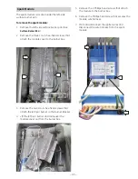
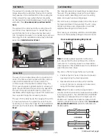
The griddle burner igniter is attached to the right
side of the griddle burner with two 1/4-in. hex-
head screws. It is necessary to remove the griddle
burner (See
Griddle Assembly
.), to access the screws
and the igniter wire harness. The griddle igniter
has a resistance value of 45 to 400
Ω
at room
temperature.
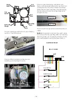
Griddle Safety Valve
Note:
The following describes the procedure to
remove the griddle safety valve. The griddle safety
valve has a resistance value of 1
Ω
or less.
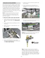
To remove the griddle safety valve:
Place the control panel in the service position.
1.
(See C
ontrol Panel
.)
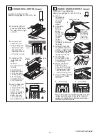
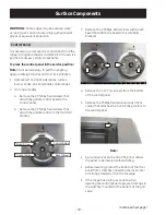
3. Disconnect the 2 wires from the valve.
4. Remove the heat barrier.
5. Remove the 9/16-in. nut from the valve.
6. Remove the two 5/16-in. hex-head nuts that
attach the valve to the chassis, then separate
the valve from the chassis and gas tube.
Disconnect (1 of 2)
Heat Barrier
Griddle Control
The control utilizes a capillary that senses griddle
temperature and a switch that operates the LED
indicator light. When the griddle knob is turned to
the ON position, the control closes contacts that
start the ignition process. The LED switch contacts
also close and activate the LED indicator light. The
LED switch can be replaced separately.
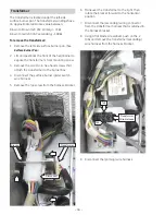
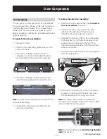
On rangetops, the griddle control is attached to a
bracket that is held in place inside the front panel.
On ranges, the griddle control is attached to a
manifold bracket.
To remove the griddle control:
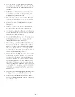
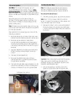
Remove the griddle, then remove the capillary
1.
retainer. (See
Griddle Assembly
.)
Note:
On range models, it’s a tight
fi
t between the
manifold bracket and the front frame of the range.
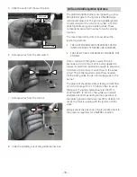
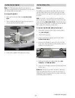
Remove the 2 Phillips-head screws and the
2.
griddle control from the control bracket
(rangetops), or manifold bracket (ranges).
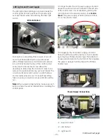
3. Place the cardboard insulator aside.
4. Slide the LED switch and switch plate off the
control shaft.
Cardboard Insulator
LED Switch
and Switch
Plate
(
Continued next page
)


