13
DEMODULATED IRIG-B
IRIG stands for Inter Range instrumentation Group, which is a standards body responsible for standardising
different time code formats. There are several different formats starting with IRIG-A, followed by IRIG-B and
so on. The letter after the "IRIG" specifies the resolution of the time signal in pulses per second (PPS). IRIG-
B, the one which we use has a resolution of 100 PPS. IRIG-B is used when accurate time-stamping is
required.
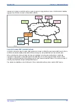
The following diagram shows a typical GPS time-synchronised substation application. The satellite RF signal
is picked up by a satellite dish and passed on to receiver. The receiver receives the signal and converts it
into time signal suitable for the substation network. IEDs in the substation use this signal to govern their
internal clocks and event recorders.
IED
IED
IED
Receiver
Satellite dish
GPS time signal
GPS satellite
V01040
IRIG-B
Figure 56: GPS Satellite timing signal
The IRIG-B time code signal is a sequence of one second time frames. Each frame is split up into ten 100
mS slots as follows:
●
Time-slot 1: Seconds
●
Time-slot 2: Minutes
●
Time-slot 3: Hours
●
Time-slot 4: Days
●
Time-slot 5 and 6: Control functions
●
Time-slots 7 to 10: Straight binary time of day
The first four time-slots define the time in BCD (Binary Coded Decimal). Time-slots 5 and 6 are used for
control functions, which control deletion commands and allow different data groupings within the
synchronisation strings. Time-slots 7-10 define the time in SBS (Straight Binary Second of day).
13.1
IRIG-B IMPLEMENTATION
Depending on the chosen hardware options, the product can be equipped with an IRIG-B input for time
synchronisation purposes. The IRIG-B interface is implemented either on a dedicated card, or together with
other communication functionality such as Ethernet. The IRIG-B connection is presented by a connector is a
BNC connector. IRIG-B signals are usually presented as an RF-modulated signal. There are two types of
input to our IRIG-B boards: demodulated or modulated. A board that accepts a demodulated input is used
where the IRIG-B signal has already been demodulated by another device before being fed to the IED. A
board that accepts a modulated input has an on-board demodulator.
To set the device to use IRIG-B, use the setting
IRIG-B Sync
cell in the
DATE AND TIME
column.
The IRIG-B status can be viewed in the
IRIG-B Status
cell in the
DATE AND TIME
column.
Chapter 7 - SCADA Communications
MiCOM P747
232
P747-TM-EN-1
P747-TM-EN-1.1
Summary of Contents for MiCOM P747 Agile
Page 2: ......
Page 16: ...Contents MiCOM P747 xiv P747 TM EN 1 P747 TM EN 1 1...
Page 20: ...Table of Figures MiCOM P747 xviii P747 TM EN 1 P747 TM EN 1 1...
Page 21: ...INTRODUCTION CHAPTER 1...
Page 22: ...Chapter 1 Introduction MiCOM P747 2 P747 TM EN 1 P747 TM EN 1 1...
Page 31: ...SAFETY INFORMATION CHAPTER 2...
Page 32: ...Chapter 2 Safety Information MiCOM P747 12 P747 TM EN 1 P747 TM EN 1 1...
Page 42: ...Chapter 2 Safety Information MiCOM P747 22 P747 TM EN 1 P747 TM EN 1 1...
Page 43: ...HARDWARE DESIGN CHAPTER 3...
Page 44: ...Chapter 3 Hardware Design MiCOM P747 24 P747 TM EN 1 P747 TM EN 1 1...
Page 74: ...Chapter 3 Hardware Design MiCOM P747 54 P747 TM EN 1 P747 TM EN 1 1...
Page 75: ...CONFIGURATION CHAPTER 4...
Page 76: ...Chapter 4 Configuration MiCOM P747 56 P747 TM EN 1 P747 TM EN 1 1...
Page 117: ...PROTECTION FUNCTIONS CHAPTER 5...
Page 118: ...Chapter 5 Protection Functions MiCOM P747 98 P747 TM EN 1 P747 TM EN 1 1...
Page 160: ...Chapter 5 Protection Functions MiCOM P747 140 P747 TM EN 1 P747 TM EN 1 1...
Page 161: ...MONITORING AND CONTROL CHAPTER 6...
Page 162: ...Chapter 6 Monitoring and Control MiCOM P747 142 P747 TM EN 1 P747 TM EN 1 1...
Page 211: ...SCADA COMMUNICATIONS CHAPTER 7...
Page 212: ...Chapter 7 SCADA Communications MiCOM P747 192 P747 TM EN 1 P747 TM EN 1 1...
Page 259: ...REDUNDANT ETHERNET CHAPTER 8...
Page 260: ...Chapter 8 Redundant Ethernet MiCOM P747 240 P747 TM EN 1 P747 TM EN 1 1...
Page 293: ...CYBER SECURITY CHAPTER 9...
Page 294: ...Chapter 9 Cyber Security MiCOM P747 274 P747 TM EN 1 P747 TM EN 1 1...
Page 313: ...SETTINGS APPLICATION SOFTWARE CHAPTER 10...
Page 314: ...Chapter 10 Settings Application Software MiCOM P747 294 P747 TM EN 1 P747 TM EN 1 1...
Page 322: ...Chapter 10 Settings Application Software MiCOM P747 302 P747 TM EN 1 P747 TM EN 1 1...
Page 323: ...BUSBAR COMMISSIONING TOOL CHAPTER 11...
Page 324: ...Chapter 11 Busbar Commissioning Tool MiCOM P747 304 P747 TM EN 1 P747 TM EN 1 1...
Page 330: ...Chapter 11 Busbar Commissioning Tool MiCOM P747 310 P747 TM EN 1 P747 TM EN 1 1...
Page 331: ...SCHEME LOGIC CHAPTER 12...
Page 332: ...Chapter 12 Scheme Logic MiCOM P747 312 P747 TM EN 1 P747 TM EN 1 1...
Page 348: ...Chapter 12 Scheme Logic MiCOM P747 328 P747 TM EN 1 P747 TM EN 1 1...
Page 349: ...INSTALLATION CHAPTER 13...
Page 350: ...Chapter 13 Installation MiCOM P747 330 P747 TM EN 1 P747 TM EN 1 1...
Page 361: ...COMMISSIONING INSTRUCTIONS CHAPTER 14...
Page 362: ...Chapter 14 Commissioning Instructions MiCOM P747 342 P747 TM EN 1 P747 TM EN 1 1...
Page 387: ...MAINTENANCE AND TROUBLESHOOTING CHAPTER 15...
Page 388: ...Chapter 15 Maintenance and Troubleshooting MiCOM P747 368 P747 TM EN 1 P747 TM EN 1 1...
Page 403: ...TECHNICAL SPECIFICATIONS CHAPTER 16...
Page 404: ...Chapter 16 Technical Specifications MiCOM P747 384 P747 TM EN 1 P747 TM EN 1 1...
Page 425: ...SYMBOLS AND GLOSSARY APPENDIX A...
Page 426: ...Appendix A Symbols and Glossary MiCOM P747 406 P747 TM EN 1 P747 TM EN 1 1...
Page 443: ...COMMISSIONING RECORD APPENDIX B...
Page 444: ...Appendix B Commissioning Record MiCOM P747 424 P747 TM EN 1 P747 TM EN 1 1...
Page 449: ...WIRING DIAGRAMS APPENDIX C...
Page 450: ...Appendix C Wiring Diagrams MiCOM P747 430 P747 TM EN 1 P747 TM EN 1 1...
Page 456: ...Appendix C Wiring Diagrams MiCOM P747 436 P747 TM EN 1 P747 TM EN 1 1...
Page 457: ......


