MAINTENANCE: Checkout Procedure
Revision D
APEX Telemetry Transmitter
3-11
401566-166
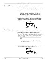
Carrier Frequency Error
This test checks the carrier frequency to verify that it is within the
programmed range.
1.
Set the RF monitor to measure 2-kHz/division horizontal.
2.
Set the meter to the 2-kHz per division scale.
3.
Remove batteries from the transmitter to power down the unit. Then
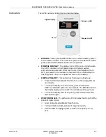
hold down the GRAPH button while installing the batteries. This
starts the transmitter is the carrier-only mode.
4.
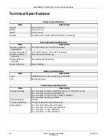
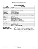
Using the RF monitor verify that the carrier signal is within ±1 kHz
of the programmed frequency, using the FE display.
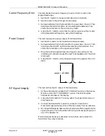
Power Output
This test measures the power output of the transmitter.
1.
Set the RF monitor to 1-MHz/division horizontal scale.
2.
Remove batteries from the transmitter to power down the unit. Then
hold down the VERIFY button while installing the batteries. This
starts the transmitter in the square-wave mode.
3.
Once the test has been started, shorting pins one and two on the
interface port connector causes the test to be repeated until the short
is removed.
4.
Using the RF monitor verify the peak output to be greater than –45
dBm.
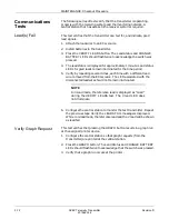
RF Signal Integrity
This test verifies the RF output of the transmitter.
1.
At the central station enable the TTX DRAW function in the Service
Monitor under the TTX DROPOUT: option. This function plots
dropout occurrences on the display.
2.
Using the DUPLICATE TTX mode, admit the transmitter to two or
more receivers.
3.
Connect the transmitter to an ECG simulator. Position the
transmitter approximately 10 to 20 feet (6 meters) from an antenna.
4.
On the admitted beds, observe the simultaneous ECG waveforms for
signal integrity. There should be no ECG signal breakup (dropout) on
any of the waveforms.
If an ECG signal breakup is observed on more than one receiver the
transmitter may require service.

