Publication No. IPN250RTM-HRM/2
Connectors 15
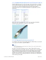
2.3.2 1000BaseKX Ethernet Channels 1 and 2 Connectors (J4 & J5)
The
IPN250RTM
supports
two
ultra
‐
thin
pipes
on
the
Control
Plane,
as
defined
by
the
OpenVPX
Payload
Slot
Profile
SLT6
‐
PAY
‐
4F1Q2UT2T
‐
10.2.1.
These
pipes
are
brought
out
to
Molex
0747030017
High
Speed
Serial
Data
(HSSDC2)
connectors
pinned
‐
out
to
the
Infiniband
Standard.
The
signal
pairs
are
100
differential.
GEIP
offers
cable
C
‐
CBL000222
‐
001,
which
is
a
2m
long
Molex
0739392003
Infiniband
cable
with
HSSDC2
connectors,
as
shown
below.
Figure 2-1 1000BaseKX Ethernet Cable
2.3.3 PCI Express Interface Connectors (J6, J7)
User
‐
defined
connections
include
4
differential
pairs
of
PCIe.
These
are
connected
as
two
ports
of
1
‐
lane
PCIe
on
the
IPN250RTM.
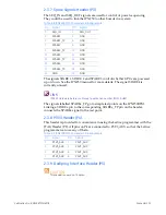
NOTE
The PCIe differential pairs can only be used as two 1-lane ports; they cannot be used together to
form a single 2-lane PCIe port.
J6
and
J7
provide
the
PCIe
interfaces
via
two
Molex
75586
‐
0007
PCI
Express
Cabling
Standard
8
‐
lane
PCIe
cable
connectors.
On
both
connectors,
only
the
first
lane
is
populated;
the
other
lanes
have
their
positive/negative
pairs
connected
together
via
100
terminating
resistors,
in
accordance
with
the
PCIe
cabling
standard.
J6
provides
lane
1
and
J7
provides
lane
2.
All
power
and
management
signals
are
unused,
and
have
been
grounded
via
100
resistors
to
maximize
the
noise
immunity
of
the
cable.
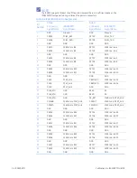
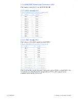
Table 2-3 IPN250RTMA J4 and J5 Pin Assignments
J4 Connector
J5 Connector
Pin
Signal
Pin
Signal
1
GND
1
GND
2
CPUTP01_RP
2
CPUTP02_RP
3
CPUTP01_RN
3
CPUTP02_RN
4
GND
4
GND
5
CPUTP01_TN
5
CPUTP02_TN
6
CPUTP01_TP
6
CPUTP02_TP
7
GND
7
GND

