GE AppliancesGeneral Electric CompanyLouisville, Kentucky 40225
31-9138
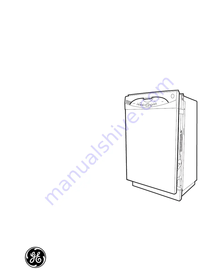
GE Built-In
Dishwasher
GLDA690GLDA696
Technical Service Guide
June 2006
GE Consumer & Industrial
Page 1: ...GE Appliances General Electric Company Louisville Kentucky 40225 31 9138 GE Built In Dishwasher GLDA690 GLDA696 Technical Service Guide June 2006 GE Consumer Industrial ...
Page 2: ... avoid personal injury disconnect power before servicing this product If electrical power is required for diagnosis or test purposes disconnect the power immediately after performing the necessary checks RECONNECT ALL GROUNDING DEVICES If grounding wires screws straps clips nuts or washers used to complete a path to ground are removed for service they must be returned to their original position an...
Page 3: ...s 11 Door Assembly 17 Door Latch and Release Assembly 13 Door Panel 11 Door Switch Assembly 15 Drain Pump Assembly 24 Fill Funnel 21 Heating Element 19 Introduction 5 Nomenclature 4 Pressure Switch 23 Schematics and Wiring Diagrams 30 Service Test Mode 28 Specifications 28 Static Dry System 12 Sump Assembly 27 Thermistor 26 Troubleshooting 29 Tub Seal 18 Warranty 31 Wash Pump Assembly 25 Water Inle...
Page 4: ...lastic bag taped behind the toe kick Nomenclature The letter designating the year repeats every 12 years Example T 1974 T 1986 T 1998 Serial Number The first two characters of the serial number identify the month and year of manufacture Example AL123456S January 2006 A JAN 2006 L D FEB 2005 H F MAR 2004 G G APR 2003 F H MAY 2002 D L JUN 2001 A M JUL 2000 Z R AUG 1999 V S SEP 1998 T T OCT 1997 S V N...
Page 5: ...ver 1 Piece Super with 1 Cell Cover Upper Rack Tiered Tiered Cycle Countdown 2 Digit Display 2 Digit Display Touchpads Knobs 9 Touchpads 9 Touchpads 120 Inlet Water Capability Yes Yes Calrod Heater Multi Wattage Multi Wattage ECONOMICAL QUIET Door Insulation and Bitumen Yes Yes Outer Wrap Full wrap Blanket Full wrap Blanket QuietPower Motor Yes Yes Sound Insulation Package QuietPower 3 58 dBA Quie...
Page 6: ... 6 Throughout this manual features and appearance may vary from your model Control Features ...
Page 7: ...DRY ON Adds approximately 38 minutes to the cycle Not available on the RINSE ONLY cycle HEATED WASH Options HEATED WASH ON Adds approximately 15 minutes to the main wash cycle Energizes heater during main wash cycle Not available on the RINSE ONLY cycle HEATED START Options HEATED START ON Adds approximately 22 minutes to the cycle by adding 2 pre rinses The first is a normal pre rinse to purge the...
Page 8: ... 8 Front View Component Locator Views Control Panel View Insulation Door Spring Access Panel Control Panel Door Latch Control Assembly Static Dry Vent Continued next page ...
Page 9: ...w With Racks Detergent Rinse Module Compartment View Top Rack Bottom Rack Detergent Rinse Module Static Dry Vent Detergent Compartment Compartment Lid Sight Glass Rinse Agent Cap Rinse Agent Outlet Continued next page ...
Page 10: ...e View Insulation Removed Bottom View Looking Up Sump Drain Pump Spray Arm Heating Element Filter Assembly Micro Filter Clamp Nut Fill Hose Pressure Switch Hose Fill Funnel Wash Pump Assembly Capacitor Pressure Switch Thermistor Water Inlet Valve Front Back ...
Page 11: ...head screws that attach the control panel to the door assembly 3 Disconnect the 3 wire harnesses from the control module 4 Vent Cover Door Panel The door panel covers the door to the dishwasher and must be removed to access the control panel detergent rinse module bottom door seal and heating element To remove the door panel remove 6 Phillips head screws then lower the door panel from the control ...
Page 12: ...cover See Static Dry System Remove the 12 Phillips head screws that attach the control circuit board to the control panel 1 2 Remove the 2 Phillips head screws that hold the control module cover to the control panel 3 Continued next page Static Dry System The static dry system operates through a vent located in the control panel The vent allows hot air to exit the dishwasher tub and gradually remo...
Page 13: ...dle is pressed upward it raises the door latch to clear the front of the door switch housing assembly releasing the door To remove the door release assembly it will be necessary to access the control panel See Control Panel steps 1 through 3 The door release is held to the control panel with 2 Phillips head screws Caution The door latch assembly may come apart Use care to assure the latch spring i...
Page 14: ...he latch block insert the latch handle hinge pins into the holes in the latch bracket 4 Raised Center Bar Latch Block Latch Handle Insert this latch assembly including the handle into the escutcheon cutout with the latch handle side toward the bottom of the escutcheon Assure that the top rib of the handle is tucked under the top edge of the cutout and attach the assembly with 2 Phillips head screw...
Page 15: ...el Remove the 2 Phillips head screws that hold the door switch assembly to the top of the door 1 2 Caution When removing the plunger the spring is not secured and will pop off To secure place your hand over the spring when removing the plunger Remove the plunger and the spring 4 Using a small flat blade screwdriver lift the door switch cover at the 2 tabs on each side the 2 inner tabs and the botto...
Page 16: ...eginning of the final rinse Operation of the detergent rinse module can be checked by using the service test mode See Service Test Mode The first time the module is activated the lever slides up the right hand path of the connecting rod 1 This action releases the detergent cover When deactivated the lever returns down the left hand path and comes to rest under the notch 2 in the center of the connec...
Page 17: ...e door hinge assembly 1 2 3 4 5 6 7 Caution When one or both of the door springs are disconnected the door may fall to the floor Care must be taken to prevent damage to the door Pull the spring and spring bolt key from the mounting bracket Remove the bottom of the spring loop from the hinge arm stud 9 10 Note The following describes the procedure to remove the right side of the door assembly from t...
Page 18: ... Position hinge arm assembly to hang freely as shown 13 Repeat steps 8 through 13 on the left side of the door panel Remove the remaining three 8 mm nuts and Phillips head screws that hold the door panel to the hinge assembly 14 15 Reverse the above procedure to install Note When installing the tub seal make sure it is seated properly in the seal channel Run your finger over the seal to make sure i...
Page 19: ...roove at the bottom of the dishwasher door WARNING The pinched metal groove is sharp Wear Kevlar gloves when removing or installing the bottom door seal Failure to comply may result in personal injury It is necessary to remove the door assembly to access the bottom door seal See Door Assembly The seal is pulled out from the pinched metal groove Door Seal Pinched Metal Groove Remove the 2 Phillips ...
Page 20: ... the 2 wires from the heating element 7 8 Remove the outer 8 mm nut that attaches the ground wire to the element mounting bolt 9 Lift the right side of the element and release it from the 2 retainers 11 Remove the inner 8 mm nut washer and spacer that attaches the element to the bottom of the tub 10 Heater Wire Heater Wire Nylon Terminal Covers Outer Nut Ground Wire Washer Inner Nut Spacer ...
Page 21: ...shwasher out from its installation Open the dishwasher door Rotate the fill funnel cap counterclockwise and remove it from the fill funnel threads 1 2 3 4 Loosen the clamp and disconnect the fill funnel hose from the fill funnel 1 Note Ensure the diverter is fully seated in the bottom of the fill funnel with the tab toward the bottom of the guides Upon assembly ensure the fill funnel gasket is placed ov...
Page 22: ...e can be checked by using the service test mode See Service Test Mode To remove the water valve Disconnect power Remove the 2 Phillips head screws washers and the access panel 1 2 Caution The clamp is easily damaged during removal and should not be reused Use the screw type hose clamp provided with the new valve Remove the clamp and the outlet hose from the valve 6 Disconnect the water supply line...
Page 23: ... water valve To remove the pressure switch Disconnect power Remove the front panel See Front Panel Remove the 2 Phillips head screws washers and the access panel 1 2 3 Remove the 2 Phillips head screws that attach the water valve and the junction box to the front brace and lower each towards the floor 4 Water Valve Junction Box Front Brace Disconnect the pink wire from terminal 1 and the yellow wir...
Page 24: ...tic tie and disconnect the 2 wires from the drain pump Remove the 2 Phillips head screws 7 mm nuts and lockwashers that hold the drain pump to the right side bottom rail 1 2 3 4 5 6 Caution The clamps are easily damaged during removal and should not be reused Remove the 2 clamps sump outlet hose and the drain hose from the drain pump 8 Remove the rubber spacer and the 2 Phillips head screws and lo...
Page 25: ...t the motor wire harness and the motor ground wire 1 2 3 4 5 Wire Harness Ground Wire Continued next page Remove the 3 clamps pump interconnect hose and outlet hoses Note Factory installed hose clamps are non reusable When installing a water inlet valve drain pump assembly wash pump assembly or sump assembly replace the old clamps with new screw type hose clamps provided The screw type hose clamps...
Page 26: ...rmistor has an approximate resistance value of 56 5K Ω at 72 F To remove the thermistor Disconnect power Open the dishwasher door and remove the bottom rack Remove the dishwasher from its installation 1 2 3 Using a small flat blade screwdriver lift each of the 2 lock tabs one on each side that hold the thermistor to the sump 6 Slide the thermistor off the sump Note Wear latex gloves to perform this...
Page 27: ...ermistor wire harness Remove the pressure switch hose from the sump 1 2 3 4 5 6 Pressure Switch Hose Sump Caution The clamps are easily damaged during removal and should not be reused Remove the 2 clamps sump outlet hose and interconnect hose from the sump Note Factory installed hose clamps are non reusable When installing a water inlet valve drain pump assembly wash pump assembly or sump assembly...
Page 28: ... MAXIMUM ACTIVATION TIME MOTOR PUMP HOT START 2 MINUTES DRAIN PUMP HOT WASH 1 MINUTE DETERGENT RINSE MODULE HEATED DRY 1 MINUTE WATER VALVE POTS PANS 1 MINUTE HEATING ELEMENT NORMAL WASH 2 MINUTES Specifications Electrical Supply Under Load 120VAC 10 Supply Water Flow Rate Must fill 1 05 gallons container in 36 seconds Supply Water Temperature 120 F to 150 F 49 C to 66 C Water Fill 1 05 gallons 4 li...
Page 29: ... o d u l e D o e s N o t W o r k W a t e r I n l e t V a l v e D o e s N o t W o r k H e a t i n g E l e m e n t D o e s N o t W o r k Control Assembly Heating Element Water Inlet Valve Detergent Rinse Module Wash Pump Drain Pump 2 Digit Display Keypad K e y p a d D o e s N o t W o r k Door Switch Assembly C o n t r o l A s s e m b l y D o e s N o t W o r k N o I n p u t P o w e r Pressure Switch ...
Page 30: ...on Label all wires prior to disconnection Wiring errors can cause improper and dangerous operation Verify operation after servicing Schematics and Wiring Diagrams Wire Colors BLACK BK WHITE WH RED RD PINK PK VIOLET VT BLUE BU YELLOW YE 1036 Ω 2 6K Ω 17 Ω 27 Ω 21 2 Ω 56 5K Ω 72 F ...
Page 31: ...in the drain line Damage caused after delivery This warranty is extended to the original purchaser and any succeeding owner for products purchased for home use within the USA Proof of original purchase date is needed to obtain service under the warranty In Alaska the warranty excludes the cost of shipping or service calls to your home Some states do not allow the exclusion or limitation of inciden...