5-130
F60 Feeder Protection System
GE Multilin
5.5 GROUPED ELEMENTS
5 SETTINGS
5
5.5.7 GROUND CURRENT
a) GROUND TIME OVERCURRENT
(ANSI 51G)
PATH: SETTINGS
ÖØ
GROUPED ELEMENTS
Ö
SETTING GROUP 1(6)
ÖØ
GROUND CURRENT
Ö
GROUND TOC1(2)
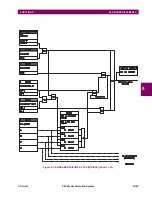
This element can provide a desired time-delay operating characteristic versus the applied current or be used as a simple
definite time element. The ground current input value is the quantity measured by the ground input CT and is the funda-
mental phasor or RMS magnitude. Two methods of resetting operation are available: “Timed” and “Instantaneous” (refer to
the
Inverse time overcurrent curve characteristics
section for details). When the element is blocked, the time accumulator
will reset according to the reset characteristic. For example, if the element reset characteristic is set to “Instantaneous” and
the element is blocked, the time accumulator will be cleared immediately.
These elements measure the current that is connected to the ground channel of a CT/VT module. The conversion
range of a standard channel is from 0.02 to 46 times the CT rating.
This channel may be also equipped with a sensitive input. The conversion range of a sensitive channel is from
0.002 to 4.6 times the CT rating.
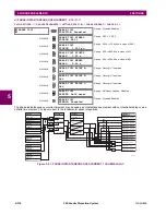
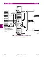
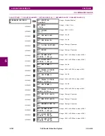
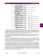
Figure 5–60: GROUND TOC1 SCHEME LOGIC
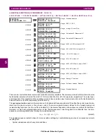
GROUND TOC1
GROUND TOC1
FUNCTION: Disabled
Range: Disabled, Enabled
MESSAGE
GROUND TOC1 SIGNAL
SOURCE: SRC 1
Range: SRC 1, SRC 2
MESSAGE
GROUND TOC1
INPUT: Phasor
Range: Phasor, RMS
MESSAGE
GROUND TOC1
PICKUP: 1.000
pu
Range: 0.000 to 30.000 pu in steps of 0.001
MESSAGE
GROUND TOC1
CURVE: IEEE Mod Inv
Range: see the Overcurrent Curve Types table
MESSAGE
GROUND TOC1
TD MULTIPLIER: 1.00
Range: 0.00 to 600.00 in steps of 0.01
MESSAGE
GROUND TOC1
RESET: Instantaneous
Range: Instantaneous, Timed
MESSAGE
GROUND TOC1 BLOCK:
Off
Range: FlexLogic™ operand
MESSAGE
GROUND TOC1
TARGET: Self-reset
Range: Self-reset, Latched, Disabled
MESSAGE
GROUND TOC1
EVENTS: Disabled
Range: Disabled, Enabled
NOTE
NOTE
S
ETT
I
NG
GROUND TOC1
FUNCTION:
Disabled = 0
Enabled = 1
S
ETT
I
NG
GROUND TOC1
SOURCE:
IG
GROUND TOC1
BLOCK:
Off = 0
FLEXLOG
I
C OPE
R
AND
S
GROUND TOC1 DPO
GROUND TOC1 OP
GROUND TOC1
CURVE:
GROUND TOC1
TD MULTIPLIER:
GROUND TOC 1
RESET:
S
ETT
I
NG
S
S
ETT
I
NG
IG
≥
PICKUP
I
t
GROUND TOC1
PICKUP:
RUN
827036A3.VSD
GROUND TOC1
INPUT:
AND
GROUND TOC1 PKP
Summary of Contents for F60 UR Series
Page 2: ......
Page 4: ......
Page 30: ...1 20 F60 Feeder Protection System GE Multilin 1 5 USING THE RELAY 1 GETTING STARTED 1 ...
Page 48: ...2 18 F60 Feeder Protection System GE Multilin 2 2 SPECIFICATIONS 2 PRODUCT DESCRIPTION 2 ...
Page 126: ...4 30 F60 Feeder Protection System GE Multilin 4 2 FACEPLATE INTERFACE 4 HUMAN INTERFACES 4 ...
Page 354: ...5 228 F60 Feeder Protection System GE Multilin 5 9 TESTING 5 SETTINGS 5 ...
Page 382: ...6 28 F60 Feeder Protection System GE Multilin 6 5 PRODUCT INFORMATION 6 ACTUAL VALUES 6 ...
Page 398: ...8 8 F60 Feeder Protection System GE Multilin 8 2 FAULT LOCATOR 8 THEORY OF OPERATION 8 ...
Page 414: ...A 14 F60 Feeder Protection System GE Multilin A 1 PARAMETER LIST APPENDIXA A ...
Page 492: ...B 78 F60 Feeder Protection System GE Multilin B 4 MEMORY MAPPING APPENDIXB B ...
Page 530: ...D 10 F60 Feeder Protection System GE Multilin D 1 IEC 60870 5 104 APPENDIXD D ...
Page 542: ...E 12 F60 Feeder Protection System GE Multilin E 2 DNP POINT LISTS APPENDIXE E ...
Page 558: ...x F60 Feeder Protection System GE Multilin INDEX ...

