background image

[EN]  English - K0449

Safety   iii

Issue 1

Safety

Before you use the instrument, make sure that you read and 
understand all the related data. This includes: the applicable 
local safety procedures, this publication, and the instructions 
for the accessories/options/equipment you are using it with.

General warnings

WARNING

It is dangerous to ignore the specified limits for the 
instrument or its related accessories. Do not use the 
instrument or accessory if it is not in its normal 
condition. Use the applicable protection and obey all 
safety precautions.

Do not use the instrument in locations with explosive 
gas, vapour or dust. There is a risk of an explosion.

Electrical warnings

To prevent electrical shocks or damage to the 
instrument, do not connect more than 30V between the 
terminals, or between the terminals and the ground 
(earth).

To prevent electrical shocks, use only the GE specified 
AC probe (Part: IO620-AC) to measure AC voltages that 
are more than 20 Vrms (maximum: 300 Vrms). Attach it 
to the specified connections only.

This instrument uses a Lithium-Polymer (Li-Polymer) 
battery pack. To prevent an explosion or fire, do not 
short circuit, do not disassemble, keep it safe from 
damage. For operating conditions, see 

Table 10-1

.

To prevent battery leakage or heat generation, only use 
the battery charger and power supply in the 
temperature range 0 to 40°C (32 to 104°F). For operating 
conditions, see 

Table 10-1

.

To make sure the display shows the correct data, 
disconnect the test leads before you set the power to on 
or change to another measure or source function. 

Pressure warnings

If you use a pressure option with the DPI 620 calibrator, these 
warnings are also applicable:

Some liquid and gas mixtures are dangerous. This 
includes mixtures that occur because of contamination. 
Make sure that the equipment is safe to use with the 
necessary media.

Continued 

Summary of Contents for Druck DPI 620

Page 1: ...GE Sensing Inspection Technologies Druck DPI 620 advanced modular calibrator user manual K0449 ...

Page 2: ... Pt1000 Pt500 Pt200 Pt100 385 0 to 2000 mV S Pt50 D 100 Ni 100 Ni 120 0 to 4000 M S 12 Thermocouples M S K J T B R S E N L U C D 0 to 50 kHz M S 20 Vrms M voltage connectors on CH1 only Switch M 2000 mV rms M voltage connectors on CH1 only 300 Vrms 50 Hz to 400 Hz M Only with the AC probe see Section 3 2 5 A1 2 DPI 620 Channel 2 CH2 30 V M 0 to 24 mA S 2000 mV M 24 V loop P maximum 24 mA 55 mA M S...

Page 3: ...arth To prevent electrical shocks use only the GE specified AC probe Part IO620 AC to measure AC voltages that are more than 20 Vrms maximum 300 Vrms Attach it to the specified connections only This instrument uses a Lithium Polymer Li Polymer battery pack To prevent an explosion or fire do not short circuit do not disassemble keep it safe from damage For operating conditions see Table 10 1 To pre...

Page 4: ... limit on the label Before you start an operation or procedure in this publication make sure that you have the necessary skills if necessary with qualifications from an approved training establishment Follow good engineering practice at all times Marks and symbols on the instrument Complies with European Union directives Warning refer to the manual Read the manual USB ports Type A Mini Type B conn...

Page 5: ...o the pressure module carrier MC 620 or to a pressure station PV 62x to give the DPI 620 calibrator the necessary pressure measurement functionality They are fully interchangeable plug and play modules with no initial set up or user calibration Pressure stations PV 62x user manual K0457 There are three pressure stations two pneumatic pressure stations to give you accurate and controlled pressure a...

Page 6: ... frequency Hz pulse count Measure simulate a Resistance Temperature Detector RTD or C F a thermocouple TC mV or C F a resistor Cold Junction CJ compensation Automatic Manual Step Ramp functions Automatic Manual Switch test and condition indicator open closed Language selection see Section 2 10 Menu sequence Universal Serial Bus USB communications ports For computer communications external modules ...

Page 7: ... software usually includes these buttons Previous view To go back to a previous page selection Next view In a sequence of page selections this takes you forward to the next page Note Different software versions have different buttons In some versions it is also necessary to set up the View to include these Tools in the Page Navigation Toolbar refer to your PDF software documentation HART Highway A...

Page 8: ...Issue 1 viii About this manual K0449 EN English ...

Page 9: ...ries 1 4 Chapter 2 Prepare the instrument 2 1 Introduction 2 1 2 2 Initial checks 2 1 2 3 Initial procedures 2 1 2 4 Power options 2 1 2 5 The battery 2 2 2 5 1 Battery condition 2 2 2 5 2 Install the battery 2 2 2 5 3 Charge the battery 2 3 2 5 4 Charge times 2 3 2 5 5 Operating time 2 3 2 6 The DC power supply 2 3 2 7 The USB power supply 2 4 2 8 Power on or off 2 4 2 9 Display operation 2 5 2 9...

Page 10: ...ion 3 1 3 2 Measure and source operations 3 1 3 2 1 Procedure overview 3 1 3 2 2 Example procedure Measure or source current 3 2 3 2 3 Example procedure Measure DC voltage 3 3 3 2 4 Example procedure Measure AC voltage CH1 0 to 20 Vrms only 3 3 3 2 5 Example procedure Measure AC voltage CH1 with the AC probe 3 4 3 2 6 Example procedure Source DC voltage CH1 3 5 3 2 7 Example procedure Measure or s...

Page 11: ... 4 5 4 5 Error indications 4 6 Chapter 5 Instrument communications 5 1 Introduction 5 1 5 2 Connect to a computer USB 5 1 Chapter 6 Datalog operation 6 1 Introduction 6 1 6 2 Set up 6 1 6 3 Data Logging 6 3 6 4 Data handling 6 3 Chapter 7 Documenting functions 7 1 Introduction 7 1 7 2 Analysis 7 1 7 3 Run a procedure 7 2 7 3 1 Sequence to upload and download file 7 3 Chapter 8 HART device operatio...

Page 12: ...Sensor Hardware Settings 8 8 8 5 2 HART menu Information Advanced Clone 8 9 8 5 3 HART menu Calibrate and Loop Test 8 10 Chapter 9 Maintenance procedures 9 1 Introduction 9 1 9 2 Clean the unit 9 1 9 3 Replace the batteries 9 1 Chapter 10 General specification 10 1 Introduction 10 1 Customer service Back cover ...

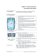
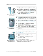
Page 13: ...2 9 Display operation To make a selection lightly tap on the applicable display area with a finger 5 Sealed speaker unit 1 2 5 3 4 Figure 1 1 General view of the instrument 2a Channel 1 CH1 connectors for V volts mV DC or AC Hz frequency and counts min counts hour cpm cph resistance RTD 2 wire 3 wire 3W 4 wire 4W resistance temperature detectors switch operation mA mA current Refer to Chapter 3 El...

Page 14: ...ion points to attach the pressure module carrier MC 620 refer to Chapter 4 Pressure indicator operation MC 620 8 Electrical connections for the pressure module carrier MC 620 or a pressure station PV 62x 9 Label model date of manufacture DoM month year serial number S N manufacturer name address website 10 Compartment cover for the battery and the optional Secure Digital cards Figure 1 4 Bottom vi...

Page 15: ... 10 d Measure or source indication Measure Source e Function voltage current pressure f Source process indicator for example Nudge Span check Ramp g Full scale FS range h Function units 3 Other windows The number of windows you see on the display is set by the number of task selections and external modules you are working with maximum 6 see Section 2 9 4 Tap this button to set up the Task set up t...

Page 16: ... carry case It can hold a set of units one DPI 620 calibrator one MC 620 module carrier PM 620 modules and related accessories 9 IO620 BATTERY Spare or replacement Li Polymer battery 10 IO620 CHARGER External battery charger to charge a battery when it is not in the instrument 11 IO620 PSU Spare DC power supply 12 IO620 USB PC USB mini Type B cable to connect the DPI 620 calibrator to a computer 1...

Page 17: ...rt IO620 HOSE P1 1 metre 39 IO620 HOSE P2 2 metre 78 18 Hydraulic hose kit rated to 1000 bar 15000 psi with Quick fit connectors for the test port IO620 HOSE H1 1 metre 39 IO620 HOSE H2 2 metre 78 19 Pressure adaptor sets designed for the MC 620 PV 62x and the hose kits IO620 BSP G1 8 G1 4 male G1 4 G3 8 and G female IO620 NPT 1 8NPT NPT male NPT 3 8NPT and NPT female IO620 MET M14 x 1 5 and M20 x...

Page 18: ...Issue 1 1 6 Instrument parts accessories and options K0449 EN English ...

Page 19: ...hand corner 2 3 Initial procedures Before you use the instrument for the first time complete these procedures Install the battery Section 2 5 2 Then re attach the cover To make sure that the calibration schedule works correctly set the date and time see Section 2 10 Menu sequence Charge the battery Section 2 5 3 2 4 Power options There are three power options Lithium Polymer battery Section 2 5 Al...

Page 20: ...DPI 620 calibrator the battery has approximately 60 of full charge You can use the battery immediately but for maximum operating time we recommend you give it a full charge Section 2 5 3 Charge indications When you set the power on the battery symbol at the top of the display shows the charge condition in 10 increments To get an accurate indication 1 increments use the Configuration menu see Secti...

Page 21: ...and a short Timeout see Section 2 10 1 Procedure to set the basic operations 2 6 The DC power supply WARNING To prevent an explosion or fire use only the GE specified battery power supply and battery charger To prevent battery leakage or heat generation only use the battery charger and power supply in the temperature range 0 to 40 C 32 to 104 F For operating conditions see Table 10 1 This unit sup...

Page 22: ...imer and then shows the applicable data To set the instrument power off press and release this button again When the power is off the last set of configuration options stays in memory 1 2 3 Step Procedure 1 Attach the applicable socket adaptor to the DC power supply 2 On the right hand side of the instrument Figure 1 3 use the rubber recess to pull down the cover for the connections 3 Push the pow...

Page 23: ...ist if applicable 2 9 2 Change numeric values There are numeric keypad displays for these items dates and times setpoint values source Automation processes Nudge Span Check calibration and other processes Tap in the necessary value on the keypad If applicable the keypad includes the buttons for and decimal point Backspace To go back one character tap this button If it is not a date or time it dele...

Page 24: ... have up to 6 functions on the display To set a Process measure operations an Automation option source operations or other Settings you must maximise the applicable function 1 2 Next keypad To use characters on the next keypad upper case lower case numeric tap this button Delete To delete the last character in the data entry box tap this button Escape If there are no characters in the data entry b...

Page 25: ...ts Utility Caption Select Function None Current Voltage A channel can only have one function at a time Section 2 10 2 Chapter 6 Chapter 7 Section 2 10 1 Section 2 12 Touch Screen lets you calibrate and re centre the screen Normally this is only necessary for versions with the Windows CE operating system TAP 1 Section 2 10 3 ...

Page 26: ...s Intensity 20 40 60 80 100 Sets the date and time The calibration function uses this to give calibration messages Date day month year dd mm yy OR month day year mm dd yy The format is factory configured Time 24 hour hours minutes seconds hh mm ss Sets the language Selected English Other languages to be released Sets the volume of the tones and alarms Volume Mute Low Medium High TAP Configuration ...

Page 27: ...n You can choose one option c Pressure function P1 for the PV 62x pressure stations refer to user manual K0457 for the MC 620 module carrier see Chapter 4 d Pressure function P2 the MC 620 module carrier can use P1 and or P2 see Chapter 4 e IDOS function Universal pressure module see Chapter 3 f HART function HART device communications see Chapter 8 If applicable change the Units for the function ...

Page 28: ... see Chapter 4 Note If you make the connections for a switch on CH1 or CH2 you cannot set another function on that channel 2 10 4 Set a function This example shows the sequence to set the Channel 1 CH1 function It is a similar procedure for other functions C B A Continued C TAP Select the function list Measure or Source Task Settings Task Settings Select Function Channel Settings 1 2 3 4 9 7 8 5 C...

Page 29: ...Minimum Average example This example shows the sequence to set the Max Min Avg utility You can use the same procedure for these options Switch Test see Chapter 3 Leak Test pressure options only see Chapter 4 Channel Settings Task Settings 7 8 TAP Task Settings 1 2 3 4 Channel Settings 5 6 Channel Settings Task Settings 7 8 TAP Task Settings 1 2 3 4 Channel Settings 5 6 Press the reset button to ge...

Page 30: ...ction 2 11 2 There are more optional Source Settings for the TC Frequency and RTD functions see Chapter 3 There are other Settings for Observed functions see Section 2 11 3 If necessary change the Settings for the pressure function item a Process Tare Alarm Filter Flow Scaling see Section 2 11 1 b Leak Test Only when the function is set up with this Utility Section 2 10 6 for operation see Chapter...

Page 31: ... a temporary value for zero This makes an adjustment to all subsequent readings on the display Alarm The alarm includes a beep sound if Audio is set Section 2 10 1 Set the tare to the reading on the display Set On or Off Shows the stored tare value Tap it to set another value Previous Back one display Home Back to start 1 2 3 TAP Set the low alarm value Set On or Off Set the high alarm value Defau...

Page 32: ...s Set On or Off Set the time constant See Definitions Previous Back one display Home Back to start 1 2 3 TAP Band The filter compares each new value with the previous value If the new value is outside the band it is not filtered Time Constant This sets the cut off frequency for the filter Higher value in seconds more filtering Set On or Off Previous Back one display Home Back to start 1 2 3 TAP ...

Page 33: ...lay Home Back to start 1 2 3 1 TAP Description Process Nudge Values to set Step Size Use these buttons to increase or decrease the output value Increments Step size Use this button Setpoint to set the output value 1 TAP Description Process Span Check Values to set Low High Dwell Use these buttons to change the value manually from High to Low Use the start and stop buttons to change the value autom...

Page 34: ...start and stop buttons to change the value automatically by the specified Step Size Dwell sets the period between each change 1 TAP Description Process Defined Step Values to set Low High Step Size Dwell Auto Repeat On Off Use these buttons to change the value manually by the specified Step Size Use the start and stop buttons to change the value automatically by the specified Step Size Dwell sets ...

Page 35: ...alibration PIN 4321 2 Tap the Accept button You can then continue with these operations Calibrate the different measure and source channels on the DPI 620 calibrator Contact us at www gesensinginspection com Change the calibration PIN You must confirm the new PIN 1 TAP Description Values to set Units enter a name for the units Resolution Set one of the 7 options 1 0 to 0 000001 Use this button Set...

Page 36: ...pgrade the software To complete this operation put the USB flash memory drive in the USB type A connector Figure 1 3 and follow the on screen instructions Upgrade the sensor firmware PM 620 To complete this operation put the USB flash memory drive in the USB type A connector Figure 1 3 and follow the on screen instructions Upgrade the HART Firmware To complete this operation put the USB flash memo...

Page 37: ...ions Section 2 11 save your settings to a file Recall When you want to use the specified settings again select the applicable filename from the list Erase One File This deletes one file from the list You must confirm that you want to delete the file Memory Status The amount of memory available in MB and as a of the total on the device internal memory USB memory micro SD card 2 13 The Help menu The...

Page 38: ...Issue 1 2 20 Prepare the instrument K0449 EN English ...

Page 39: ...3 3 2 1 Procedure overview To use the calibrator complete these procedures Set the calibrator functions you want to use on the display item see Section 2 10 3 This includes a CH1 Channel 1 electrical function measure or source b CH2 Channel 2 electrical function measure or source c Pressure function P1 and or P2 for the MC 620 module carrier see Chapter 4 for the PV 62x pressure stations P1 only r...

Page 40: ...e TC Frequency and RTD functions There are other Settings for Observed functions see Section 2 11 3 When all the software selections are complete make the applicable electrical connections 3 2 2 Example procedure Measure or source current These examples A and B show Channel 1 CH1 set up to measure or source a current with external loop power Note If you use the Channel 2 CH2 connectors you can use...

Page 41: ...Channel 2 CH2 to measure these ranges 1 Set the applicable software options see Section 3 2 1 Procedure overview 2 Complete the electrical connections and continue with the measure operation 3 2 4 Example procedure Measure AC voltage CH1 0 to 20 Vrms only WARNING To prevent electrical shocks use only the GE specified AC probe Part IO620 AC to measure AC voltages that are more than 20 Vrms maximum ...

Page 42: ...voltages that are more than 20 Vrms maximum 300 Vrms Attach it to the specified connections only This example shows Channel 1 CH1 set up to measure an AC voltage with the AC probe maximum 300 Vrms 1 Set the applicable software options for the AC Probe see Section 3 2 1 Procedure overview 2 Complete the electrical connections Red V Hz connector Black COM connector Then continue with the measure ope...

Page 43: ... procedure Measure or source current with internal 24V loop power These examples A and B show Channel 2 CH2 set up to measure or source a current with internal loop power 24 V 2 1 3 Source DC volts on channel 1 CH1 Range 0 to 12 V DC Automation Nudge Section 2 11 2 A Source DC millivolts on channel 1 CH1 Range 0 to 2000 mV DC Automation Nudge Section 2 11 2 B 1 3 2 2 1 Measure current on channel 2...

Page 44: ...m or cph The selection of units sets the available range for example Example A 1 Set the applicable software options see Section 3 2 1 Procedure overview 2 Complete the electrical connections 3 If necessary change the Trigger Level Settings and continue with the measure operation Values to set Mode Automatic Manual Manual Level trigger level value Example B 1 Set the applicable software options se...

Page 45: ... set up to measure or simulate an RTD A 4 Wire configuration gives the best accuracy a 2 Wire configuration has the lowest accuracy 4 Wire RTD shown Note To measure or simulate resistance set the Resistance function Example A 1 Set the applicable software options see Section 3 2 1 Procedure overview 2 Complete the electrical connections 3 If necessary change the Settings and continue with the meas...

Page 46: ...ns 4 Automation Set the applicable output value see Section 2 11 2 3 2 10 Example procedure Measure or simulate a thermocouple or TC mV These examples A and B show Channel 1 CH1 set up to measure or simulate a thermocouple temperature Note To measure or simulate TC millivolts set the TC mV function Example A 1 Set the applicable software options see Section 3 2 1 Procedure overview 2 Complete the ...

Page 47: ...Automatic Manual Automatic uses the internal cold junction Use Manual mode when you want to use an external cold junction CJ Value For Manual mode set an applicable value The value is not used in Automatic mode 4 Automation Set the applicable output value see Section 2 11 2 3 2 11 Example procedure Switch test CH1 P1 P2 and IDOS functions use the CH2 switch connections CH2 functions use the CH1 sw...

Page 48: ...te switch value set a long Travel period Use Start Stop to start and stop the Ramp cycle If necessary supply the output values in the opposite direction until the switch changes condition again 4 The display shows the values to open and close the switch the hysteresis value 5 To do the test again use the reset button 3 3 Measure pressure IDOS option Optional item An IDOS Universal Pressure Module ...

Page 49: ...ary change the Units for the function item see Section 2 10 5 If necessary set a Utility for the function item see Section 2 10 6 a Max Min Avg b Switch Test Step Procedure 1 Attach one end of the adaptor IO620 IDOS USB to the applicable IDOS module 2 On the right hand side of the instrument Figure 1 3 use the rubber recess to pull down the cover for the connections 3 Push the Type A end of the ad...

Page 50: ...bly see Section 4 4 2 c Zero The procedure is the same for an IDOS module or for a PM 620 module see Section 4 4 3 We recommend that you zero a gauge sensor before you use it Continue with the pressure operation 3 3 3 Example procedure Measure pressure with an IDOS module 1 Assemble the DPI 620 calibrator and the IDOS module see Section 3 3 1 2 To attach the external pressure equipment refer to th...

Page 51: ...or over range Make sure that the range is correct Make sure that all the related equipment and connections are serviceable Under range The display shows this symbol for this condition Reading Negative FS 10 of negative FS Over range The display shows this symbol for this condition Reading Positive FS 10 of positive FS ...

Page 52: ...Issue 1 3 14 Electrical and IDOS operations K0449 EN English ...

Page 53: ... assembly This figure shows the parts of the module carrier MC 620 and pressure module PM 620 When you attach these items to the DPI 620 calibrator you have a fully integrated pressure indicator that can measure pneumatic or hydraulic pressure Caution To prevent damage to the PM 620 module only use it within the specified pressure limit on the label 1 2 3 4 1 2 3 b PM 620 a MC 620 5 a 1 Pressure c...

Page 54: ... tighten the two screws until they are hand tight 3 Attach one or two PM 620 modules with the correct range and type 4 Tighten each one until it is hand tight only When this symbol flashes at the top of the display it shows there is communication between the module and the calibrator Step Procedure 1 Remove the adaptor from the pressure port 2 Use an applicable seal for the pressure connection a N...

Page 55: ... 2 electrical function measure or source d other functions maximum 6 functions If necessary change the Units for the function item see Section 2 10 5 If necessary set a Utility for the function item see Section 2 10 6 a Max Min Avg b Switch Test c Leak Test see Section 4 4 2 If necessary change the Settings for the pressure function item a Process Tare Alarm Filter Flow Scaling see Section 2 11 1 ...

Page 56: ...you can set these options Wait Time The time before the test starts in hours minutes seconds hh mm ss Test Time The period of the leak test in hours minutes seconds hh mm ss Note To set the Leak Test options you must have a pressure module correctly installed Section 4 2 1 2 1 3 4 Select Leak Test Select Test Time Steps 5 and 6 Set the Test Time Set the Wait Time if necessary TAP the window Maximi...

Page 57: ...ondition Note To make a temporary adjustment for zero you can use the Tare function see Section 2 11 1 4 4 4 Example procedure Measure pressure 1 Assemble the pressure indicator with the correct PM 620 modules see Section 4 2 1 Adjustment d 10 FS positive pressure value for the Sensor 2 1 3 4 Select Zero Accept the adjustment value TAP the window Maximise Select Settings See the new reading 5 Go b...

Page 58: ...To attach the external equipment see Section 4 3 1 4 5 Error indications If the display shows under range or over range Make sure that the range is correct Make sure that all the related equipment and connections are serviceable Under range The display shows this symbol for this condition Reading Negative FS 10 of negative FS Over range The display shows this symbol for this condition Reading Posi...

Page 59: ...se the DC power supply Section 2 6 When the connections are complete you can move files between the computer and the DPI 620 calibrator with your normal file manager software for example Windows Explorer If you install a USB flash memory device and a micro SD card the computer can only see the micro SD card It ignores the USB memory device Note The computer cannot get access to the internal memory...

Page 60: ...Issue 1 5 2 Instrument communications K0449 EN English ...

Page 61: ...USB stick Wireless to be released later USB serial port To enter data logging select configuration menu and press data logging 6 2 Set up To set the data logging process After data logging the data file can be used in the data logging menu as follows Selection Action Filename Enter name using three page screen alpha numeric key pad Trigger Set to Key Press to activate on pressing of bottom right k...

Page 62: ...rse sequence Transfer The stored data held in the internal memory can be transferred to an external memory device USB stick Wireless to be released later USB serial port Erase Erase one file Select file to erase Clear internal erases all files held in the instrument s memory Clear USB stick erases all data on the USB stick detected at the USB port Clear SD card erases all data on the installed SD ...

Page 63: ... logging The display changes to the task screen with data logging flashing at the top If necessary press play pause to increment the data logging At the end of data logging press the cancel key The instrument stores the recorded data 6 4 Data handling Using the data logging menu a data file can be replayed stored in a memory device or transferred to an external device see Section 6 2 The data file...

Page 64: ...Issue 1 6 4 Datalog operation K0449 EN English ...

Page 65: ... then gives a pass or fail indication Run Procedure Section 7 3 This uses the Intecal Calibration software Optional item to download a calibration procedure Before you start Read and understand the Safety section Do not use a damaged instrument Note Use only original parts supplied by the manufacturer 7 2 Analysis To use the Analysis function set the functions for the two Channels you want to comp...

Page 66: ...values to calibrate a device under test test points ramp time You can use the same calibration procedure for all the applicable devices under test To use the Run Procedure function you need these items a copy of the Intecal Calibration Software This is available from our website at www gesensinginspection com There is a 30 day free trial IO620 USB RS232 Intecal version 5 only An adaptor to connect...

Page 67: ... the Download button in Intecal to download the file to the DPI 620 calibrator During this process there is a communications symbol at the bottom of the display 5 Tap the Run Procedure option 6 In the Results window that opens select the Filename you specified in Intecal 7 Enter your User ID and the DUT Serial Number 8 Tap on the Start button The Procedure sets up the necessary Channel options for...

Page 68: ...Issue 1 7 4 Documenting functions K0449 EN English ...

Page 69: ...ital signal on top of a standard 4 20 mA current loop to get data to and from a HART enabled field device These operations are typical read the primary variable and the analogue output read the device serial number type and supplier get calibration data upper and lower range values sensor limits calibration date do status and fault finding checks change the device configuration range units damping...

Page 70: ...serial number upper lower transducer limits minimum span 14 Hart Sensor Info Universal 5 Primary damping value write protect mode alarm 15 Hart Sensor Info Universal 5 Write Tag descriptor and date 18 Hart hardware info Universal 5 Write primary damping factor 34 Hart Sensor Info Common 5 Write primary variable range values LRV URV 35 Re range menu Common 5 Set primary URV Span 36 Re range menu Co...

Page 71: ...damping factor 64 Advanced analogue menu Common 5 Write analogue channel range values 65 Advanced analogue menu Common 5 Enter Exit fixed analogue output mode 66 Loop test Common 5 Trim analogue channel zero 67 Trim Menu multiple output device Common 5 Trim analogue channel gain 68 Trim Menu multiple output device Common 5 Write analogue channel transfer function 69 Analogue channel info Common 5 ...

Page 72: ...tion 8 Advanced device menu Universal 6 Read device variable trim points 80 Trim Menu Common 6 Read device variable trim guidelines 81 Trim Menu Common 6 Write device variable trim point 82 Trim Menu Common 6 Reset device variable trim 83 Trim Menu Common 6 Read burst mode configuration 105 Hart settings menu Common 6 Write burst mode configuration 109 Hart settings menu Common 5 Command name Comm...

Page 73: ...ion see Section 8 5 8 4 2 External loop power In this example there is an external power supply 1 Set the functions for channel 2 and HART e 2 Set to On Section 2 9 a b c d Home display TAP Measure current on channel 2 CH2 Range 55 mA HART Function is set 250 resistor is set Maximum 30V e 1 a b d c Set HART Section 2 10 4 Set Current Measure Section 2 10 4 Home display TAP ...

Page 74: ... 4 3 Communicator attached to a network In this example the calibrator connects directly to a network There must be a 250 resistor in series with the loop power supply and the HART device 1 Set the function for HART e 2 Set to On Section 2 9 a b c d Home display TAP No functions on channel 2 CH2 HART Function is set 250 resistor is set to Off d 1 a b c Set HART Section 2 10 4 Home display TAP ...

Page 75: ...erations 8 7 Issue 1 2 If necessary set the HART Resistor in the Advanced menu to Off 3 Complete the electrical connections and continue with the HART menu operation see Section 8 5 e 2 Set to Off Section 2 9 a b c d Home display TAP ...

Page 76: ...sequence of steps for all the power supply options 8 5 1 HART menu Information Sensor Hardware Settings 5 6 Continue into the HART menu structure 7 Go back to the Home display This shows the primary variable and the loop current supplied in digital form by the HART device 1 2 7 4 Home display 3 6 3 to 5 Set the search options and continue 2 Select Search 1 Start all HART selections from the HART m...

Page 77: ...cations Section 8 5 2 Go to the Clone menu option and tap on Copy It copies these parameters 3 Go back to the Home display and attach the other field device 4 Start communications with the new device Section 8 5 5 Go to the Clone menu option and tap on Paste To complete the Clone operation from one device to another make sure the DPI 620 calibrator stays on for the whole procedure 1 See Section 8 ...

Page 78: ...current is set to 4 000 mA but the actual loop current is 4 0123 mA To trim the error make a note of the actual reading 4 0123 and enter this value in Analogue Trim Zero Step 8 1 1 Loop Test On 2 Test Value 4 000 mA 3 Go to Home display 1 2 3 6 5 4 4 Actual value 4 0123 5 HART menu 6 Calibrate 7 7 Trims 8 8 Enter Trim Zero 4 0123 ...

Page 79: ...an approved organisation that collects and or recycles waste electrical and electronic equipment For more information contact one of these our customer service department Contact us at www gesensinginspection com your local government office 9 2 Clean the unit Clean the case with a moist lint free cloth and a weak detergent Do not use solvents or abrasive materials 9 3 Replace the batteries To rep...

Page 80: ...Issue 1 9 2 Maintenance procedures K0449 EN English ...

Page 81: ...tection IP65 DPI 620 calibrator only Humidity 0 to 90 relative humidity RH non condensing Shock Vibration Def Stan 66 31 8 4 cat III EMC Electromagnetic compatibility BS EN 61326 1 2006 Electrical safety Electrical BS EN 61010 2001 Pressure safety Pressure Equipment Directive Class Sound Engineering Practice SEP Approved CE Marked Battery power Lithium Polymer battery GE Part number 191 356 Capaci...

Page 82: ...Issue 1 10 2 General specification K0449 EN English ...

Page 83: ...Customer service Visit our web site www gesensinginspection com ...

Page 84: ......

Reviews: