


March 2008
C-2
Optional Enclosures
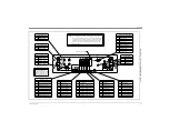
Rack Mount Wiring
(cont.)
3.
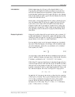
Wire the 0/4-20 mA
analog outputs
at the left side of the rear
panel in accordance with the instructions in Chapter 1,
Installation
, of this manual.
4.
Wire the
RS232 serial port
by completing the following steps:
a.
Purchase or prepare a suitable serial cable. This cable should
have a standard female DB9 connector, wired as shown in
Figure C-2 on page C-4, for connection to the rear panel of the
Model GS868. The other end should be as required for the
external device.
b.
Complete the serial port wiring in accordance with the
instructions in Chapter 1,
Installation
, of this manual.
5.
Wire any installed
option cards
using the same procedures
described in Chapter 1,
Installation
, of this manual and the pin #
assignments shown in Figure C-2 on page C-4.
Note:
The pins on the option card connectors are numbered from pin
#1 on the top to pin #8 (or #9) on the bottom.
6.
Place the
power switch
(item #1) in the ON position.
The Model GS868 is now completely wired. Proceed to Chapter 2,
Initial Setup
, of this manual for further instructions.
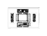
Rack Mount Front Panel
The keypad and LCD display for the rack mount Model GS868 are
located on the front panel. These items are identical in form and
function to those used on the standard Type-4X enclosure, but the
layout is somewhat different.
Refer to Figure C-3 on page C-5 for the front panel layout of the rack
mount Model GS868 and follow the standard procedures detailed in
the main body of this manual.
Summary of Contents for DigitalFlow GS868
Page 6: ...Chapter 1...
Page 28: ...Chapter 2...
Page 40: ...Chapter 3...
Page 41: ...Operation Introduction 3 1 Powering Up 3 2 Using the Display 3 3 Taking Measurements 3 5...
Page 49: ...Chapter 4...
Page 50: ...Specifications General 4 1 Electrical 4 2 Operational 4 4 Transducer 4 4 Flowcell 4 5...
Page 56: ...Appendix A...
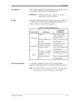
Page 57: ...CE Mark Compliance Introduction A 1 Wiring A 1 External Grounding A 1...
Page 59: ...Appendix B...
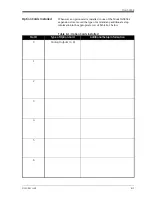
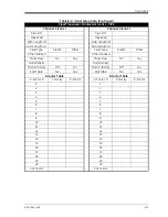
Page 60: ...Data Records Option Cards Installed B 1 Initial Setup Data B 2...
Page 64: ...Appendix C...
Page 71: ...Appendix D...
Page 72: ...Measuring P and L Dimensions Introduction D 1 Measuring P and L D 1...


