628
D90
PLUS
LINE DISTANCE PROTECTION SYSTEM – INSTRUCTION MANUAL
THE D90
Plus
DISTANCE ELEMENTS
CHAPTER 15: THEORY OF OPERATION
•
Positive-sequence voltage is between 0.8 and 1.2 pu.
•
Source frequency differs from tracking frequency by less than 0.5 Hz.
•
Source frequency differs from nominal frequency by less than 5.5 Hz.
•
No open pole condition exists.
If these conditions are not met, then the time-domain algorithm is not armed and the
D90
Plus
will trip from the frequency domain algorithm if required. If the conditions are met,
then the arming logic will open a two-cycle window that begins when the disturbance is
detected. During this two-cycle period, the time domain algorithm will operate if required.
After this window expires, the time domain algorithm cannot be re-armed for another five
cycles.
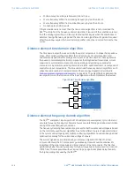
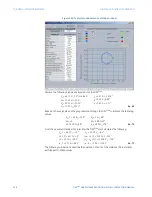
Distance element time domain algorithm
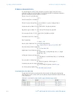
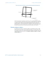
The time domain algorithm uses virtually the same comparators to shape the impedance
zones. Short-window orthogonal filters (h
D
and h
G
) are used to calculate direct and
quadrature axis quantities for voltage and current in the time domain. These signals are
then used to calculate symmetrical components, fast magnitudes (for example, current
supervision), symmetrical components, and operating and polarizing quantities for
comparators. A particular operating characteristic (mho, quadrilateral, etc.) is composed of
several two-input comparators. The time domain and frequency domain algorithms each
utilize the same number of comparators and the same input signals as described in
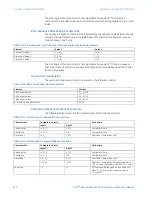
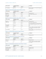
Distance element characteristic summary
on page 634. The only difference between the
two algorithms is in the formation of the input signals and the comparators themselves.
Figure 546: Time domain algorithm
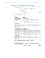
Distance element frequency domain algorithm
The D90
Plus
samples AC input signals at 128 samples per power system cycle. A fast and
accurate frequency tracking mechanism ensures accurate filtering and phasor estimation
during off-nominal frequency conditions.
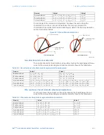
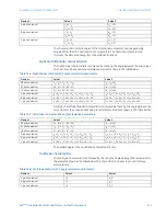
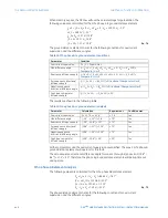
The frequency domain phasor estimation process for both currents and voltages is based
on the commonly used Fourier algorithm. Due to the different nature of signal distortions
in the current and voltage signals, digital pre-filtering algorithms have been designed and
optimized separately for the current and voltage channels.
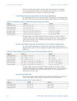
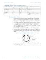
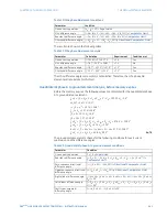
The current signals are pre-filtered using an improved digital MIMIC filter. The filter
removes effectively the DC components, guaranteeing transient overshoot below 2%
regardless of the initial magnitude and time constant of the components. The filter has
significantly better frequency response for higher frequencies as compared to a classical
MIMIC filter. This was possible without introducing any significant phase delay thanks to
the high sampling rate used by the D90
Plus
.
&XUUHQW
K
'
K
4
9ROWDJH
K
'
K
4
'LVWDQFHWHUPV
î ²
HWF
, = 9 9
SRO
$&'5
6\PPHWULFDOFRPSRQHQWV
HWF
9 9
0DJQLWXGHV
HWF
, ,
$ %


