CHAPTER 7: PROTECTION
GROUPED PROTECTION ELEMENTS
D90
PLUS
LINE DISTANCE PROTECTION SYSTEM – INSTRUCTION MANUAL
261
Pos Seq Restraint
Range: 0.000 to 0.500 in steps of 0.001
Default: 0.063
This setting controls the amount of the positive-sequence restraint. Set to zero to
remove the restraint. Set to a higher value if large system unbalances or poor CT
performance are expected.
Forward ECA
Range: 0 to 90° Lag in steps of 1
Default: 75° Lag
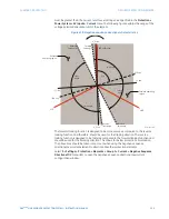
This setting specifies the element characteristic angle (ECA) for the forward direction.
The element characteristic angle in the reverse direction is the angle set for the forward
direction shifted by 180°.
Forward Limit Angle
Range: 40 to 90° in steps of 1
Default: 90°
This setting specifies a symmetrical limit angle (in both directions from the element
characteristic angle) for the forward direction.
Forward Pickup
Range: 0.015 to 30.000 pu in steps of 0.005
Default: 0.050 pu
This setting specifies the pickup level for the overcurrent unit in the forward direction.
This pickup threshold applies to zero or negative-sequence current based on the
Type
setting. When specifying this setting, it must be kept in mind that the design uses a
positive-sequence restraint technique.
Reverse Limit Angle
Range: 40 to 90° in steps of 1
Default: 90°
This setting specifies a symmetrical limit angle (in both directions from the element
characteristic angle) for the reverse direction.
Reverse Pickup
Range: 0.015 to 30.000 pu in steps of 0.005
Default: 0.050 pu
This setting specifies the pickup level for the overcurrent unit in the reverse direction.
This pickup threshold applies to zero or negative-sequence current based on the
Type
setting. When specifying this setting, it must be kept in mind that the design uses a
positive-sequence restraint technique.
Block
Range: any FlexLogic™ operand or shared operand
Default: Off
Assertion of the operand assigned to this setting blocks operation of the negative-
sequence directional overcurrent element.
Events
Range: Enabled, Disabled
Default: varies with UR
Plus
-series model; refer to the EnerVista UR
Plus
Setup software
This setting enables and disables the logging of negative-sequence directional
overcurrent events in the sequence of events recorder.
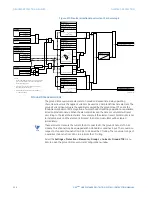
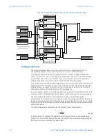
The logic for the negative-sequence directional overcurrent 1 element is shown below. The
logic is identical for all negative-sequence directional overcurrent elements.

