CHAPTER 7: PROTECTION
GROUPED PROTECTION ELEMENTS
D90
PLUS
LINE DISTANCE PROTECTION SYSTEM – INSTRUCTION MANUAL
255
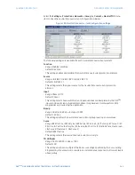
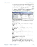
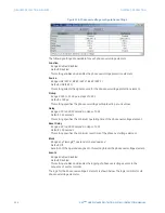
Source
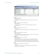
Range: LINE (SRC 1), BKR 1 (SRC 2), BKR 2 (SRC 3)
Default: LINE (SRC 1)
This setting selects the signal source for the negative-sequence time overcurrent
protection element.
Pickup
Range: 0.000 to 30.000 pu in steps of 0.001
Default: 1.000 pu
This setting specifies the neutral time overcurrent pickup level in per-unit values.
Curve
Range: IEEE Mod Inv, IEEE Very Inv, IEEE Ext Inv, IEC Curve A, IEC Curve B, IEC Curve C, IEC
Short Inv, IAC Ext Inv, IAC Very Inv, IAC Inverse, IAC Short Inv, I2t, Definite Time, FlexCurve A,
FlexCurve B, FlexCurve C, FlexCurve D
Default: IEEE Mod Inv
This setting selects the inverse time overcurrent curve style.
TD Multiplier
Range: 0.00 to 600.00 in steps of 0.01
Default: 1.00
This setting specifies a multiple of the base curve shape specified by the
Curve
setting.
Programming this value to zero results in an instantaneous response to all current levels
above pickup.
Reset
Range: Instantaneous, Timed
Default: Instantaneous
The “Instantaneous” reset method is intended for applications with other relays, such as
most static relays, which set the energy capacity directly to zero when the current falls
below the reset threshold. The “Timed” reset method can be used where the relay must
coordinate with electromechanical relays.
Block
Range: any FlexLogic™ operand or shared operand
Default: Off
Assertion of the operand assigned to this setting blocks operation of the negative-
sequence time overcurrent element.
Events
Range: Enabled, Disabled
Default: varies with UR
Plus
-series model; refer to the EnerVista UR
Plus
Setup software
This setting enables and disables the logging of negative-sequence time overcurrent
events in the sequence of events recorder.
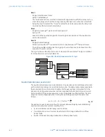
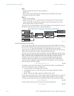
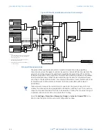
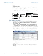
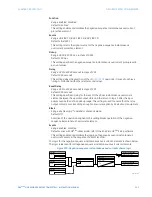
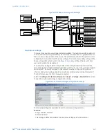
The logic for the negative-sequence time overcurrent 1 element is shown below. The logic
is identical for all negative-sequence time overcurrent elements.

