CHAPTER 7: PROTECTION
GROUPED PROTECTION ELEMENTS
D90
PLUS
LINE DISTANCE PROTECTION SYSTEM – INSTRUCTION MANUAL
195
NOTE
NOTE:
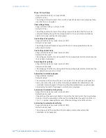
The use of dynamic reach control by selection of a non-zero value for the
Voltage Level
setting will disable the subcycle operating time for that particular zone.
Delay
Range: 0.000 to 65.535 seconds in steps of 0.001
Default: 0.000 seconds
This setting allows the user to delay operation of the distance elements and implement
stepped distance protection. The distance element timers for zones 2 through 5 apply a
short dropout delay to cope with faults located close to the zone boundary when small
oscillations in the voltages or currents could inadvertently reset the timer. Zone 1 does
not need any drop out delay since it is sealed-in by the presence of current.
Block
Range: any FlexLogic™ operand
Default: OFF
This setting enables the user to select a FlexLogic™ operand to block a given distance
element. VT fuse fail detection is one of the applications for this setting.
Events
Range: Enabled, Disabled
Default: Enabled
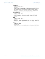
This setting enables and disables the logging of phase distance events in the sequence
of events recorder.
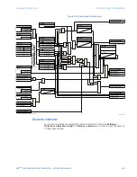
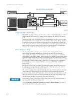
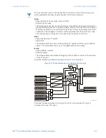
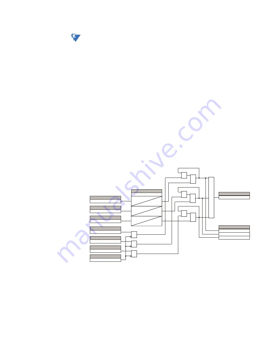
The phase distance operation scheme logic for zone 1 is shown below.
Figure 171: Phase distance zone 1 operation scheme logic
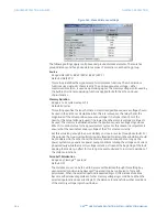
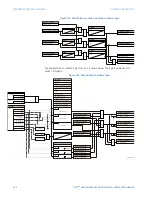
The phase distance operation scheme logic for zone 2 is shown below. The logic is
analogous for zones 3 through 5.
25
$1'
$1'
$1'
$&'5
3+',67=3.3$%
)/(;/2*,&23(5$1'
3+',67=3.3%&
3+',67=6831,$%
3+',67=3.3&$
3+',67=6831,&$
3+',67=6831,%&
23(132/(23
7SNS
'HOD\
6(77,1*
7SNS
7SNS
)/(;/2*,&23(5$1'
)/(;/2*,&23(5$1'
)/(;/2*,&23(5$1'
)/(;/2*,&23(5$1'
)/(;/2*,&23(5$1'
)/(;/2*,&23(5$1'
3+',67=23
)/(;/2*,&23(5$1'
3+',67=23%&
)/(;/2*,&23(5$1'6
3+',67=23$%
3+',67=23&$
$1'
$1'
$1'
25
25
25

