


Revision D
250 Series Maternal/Fetal Monitor
5-7
2020551-001
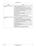
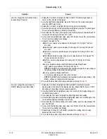
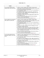
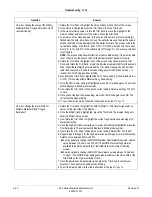
Troubleshooting:
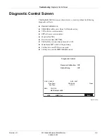
Diagnostic Control Screen
Run Time
This field displays the amount of time the monitor has been turned on—since the
field was cleared. The time is displayed in hours, minutes, and seconds. To clear this
field (reset the timer), activate the
Clear
softkey to the right of the run time field.
NOTE:
The
Clear
softkey also resets the recorder time field.
Recorder Time
This field displays the amount of time the recorder has been turned on (or printing in
maternal-only mode)—since the field was cleared. The time is displayed in hours,
minutes, and seconds. To clear this field (reset the timer), activate the
Clear
softkey
to the right of the recorder time field.
NOTE:
The
Clear
softkey also resets the monitor run time field.
Recorder Servicing
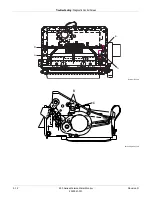
Removing the Strip Chart Recorder
Removing the strip chart recorder requires
loosening
the monitor’s front panel bezel.
Following this procedure carefully will avoid unnecessary damage to bezel’s
mounting screws and the unit’s front panel connectors.
1. Turn off the 250 Series Monitor and disconnect the power cord from the
monitor.
2. Remove the nine screws which secure the monitor top cover. Four screws are
located on the bottom of the monitor and five screws are located in the back.
3. Remove the cover by sliding it toward the rear of the monitor.
4. Remove the four screws that attach the recorder bracket to the bottom of the
chassis.
5. Remove the two screws which fasten the right and left sides of the bezel away
to the chassis.
6. Disconnect the display ribbon cable from the DSP Board at J5.
7. Disconnect the ribbon cable from the DSP Board.
8. Disconnect the ribbon cable from the Recorder Board at J2. Leave the other end
connected to the Main Motherboard.
9. Disconnect the Power Supply cable harness from the Recorder Board at J1.
10. Lift the recorder and its attached bracket out of the monitor.
Installing the Strip Chart Recorder
1. Carefully place the recorder into the monitor housing and reassemble to the
chassis bottom with four screws.
2. Re-connect the Power Supply cable harness to the Recorder Board at J1.
Summary of Contents for Corometrics 250 Series
Page 2: ......
Page 6: ...CE CE ii 0086 ...
Page 14: ...viii 250 Series Maternal Fetal Monitor Revision D 2020551 001 ...
Page 16: ...1 2 250 Series Maternal Fetal Monitor Revision D 2020551 001 For your notes ...
Page 29: ...Revision D 250 Series Maternal Fetal Monitor 2 1 2020551 001 2 Equipment Overview ...
Page 30: ...2 2 250 Series Maternal Fetal Monitor Revision D 2020551 001 For your notes ...
Page 55: ...3 1 250 Series Maternal Fetal Monitor Revision D 2020551 001 3 Installation ...
Page 56: ...3 2 250 Series Maternal Fetal Monitor Revision D 2020551 001 For your notes ...
Page 81: ...Revision D 250 Series Maternal Fetal Monitor 4 1 2020551 001 4 Maintenance ...
Page 82: ...4 2 250 Series Maternal Fetal Monitor Revision D 2020551 001 For your notes ...
Page 143: ...Revision D 250 Series Maternal Fetal Monitor 5 1 2020551 001 5 Troubleshooting ...
Page 144: ...5 2 250 Series Maternal Fetal Monitor Revision D 2020551 001 For your notes ...
Page 196: ...6 2 250 Series Maternal Fetal Monitor Revision D 2020551 001 For your notes ...
Page 239: ...Revision D 250 Series Maternal Fetal Monitor B 1 2020551 001 B Alarms Summary ...
Page 240: ...B 2 250 Series Maternal Fetal Monitor Revision D 2020551 001 Alarms Summary For your notes ...
Page 243: ...Revision D 250 Series Maternal Fetal Monitor C 1 2020551 001 C Electromagnetic Compatibility ...
Page 251: ......