

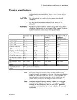

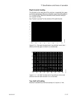

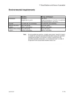


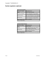


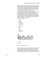


Ventilator theory
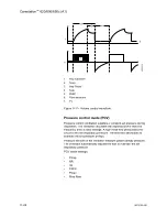
The ventilator engine is located in the middle pan of the system,
under the user work surface. A precision flow servo system controls
gas flow to the patient. During inspiration, this gas flow closes the
exhalation valve and pushes the bellows down. During expiration, a
small flow pressurizes the exhalation diaphragm to supply PEEP
pressure. If the maximum pressure (Pmax) is reached during
inspiration, the ventilator will cycle to expiration.
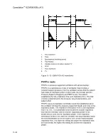
Volume and flow measurements come from flow sensors in the
breathing system. Two tubes from each sensor connect to a
transducer that measures the pressure change across the sensor,
which changes with the flow. A third transducer measures airway
pressures at the inspiratory flow sensor.
The ventilator uses the data from the flow sensors for volume-related
numerics and alarms. Numerics come from the flow sensor data if
Data source is set to Vent. If Data source is set to patient, numerics
come from the airway module and the patient icon shows in the
numerics field. The ventilator also uses the flow sensors to adjust its
output for changes in fresh gas flow, small leaks, and gas
compression upstream of the breathing circuit. There is adjustment
for compression in the patient circuit.
In volume ventilation modes, certain alarm conditions prevent the
automatic adjustment of ventilator delivery based on measured flow
values. In these cases, ‘TV accuracy decreased. Adjust manually.’
displays above the ventilator setting area of the screen. When this
message shows, the ventilator may not be able to deliver within the
accuracy range specified. When this occurs, the tidal volume must
be manually adjusted until the volume delivered reaches the desired
level. If compensation stops for a number of breaths, the condition
causing the hold shows as an alarm. Automatic volume
compensation resumes when the alarm conditions are resolved.
For better precision a small quantity of gas bleeds through a resistor
to keep pressure on the exhalation valve constant. At high airway
pressures, this can cause a slight hiss during inspiration.
Do not use the system if the
‘No exp flow sensor’
alarm is
active. If the expiratory flow sensor is not installed
correctly, the patient disconnect alarm will not operate
correctly.
O2 monitoring theory of operation
O2 monitoring measures O2 concentration in the patient circuit. The
O2 concentration measured from the O2 cell is shown on the
anesthesia system display.
The O2 cell is an electrochemical device (galvanic cell). Oxygen
diffuses through a membrane into the cell and oxidizes a base metal
WARNING
11 Specifications and theory of operation
2076152-001
11-23
Summary of Contents for Carestation 620
Page 1: ...Carestation 620 650 650c A1 User s Reference Manual Software Revision 01...
Page 12: ...Carestation 620 650 650c A1 x 2076152 001...
Page 58: ...2 24 2076152 001...
Page 98: ...3 40 2076152 001...
Page 102: ...4 4 2076152 001...
Page 128: ...6 12 2076152 001...
Page 150: ...7 22 2076152 001...
Page 182: ...8 32 2076152 001...
Page 196: ...9 14 2076152 001...
Page 246: ...11 44 2076152 001...
Page 268: ...Carestation 620 650 650c A1 User s Reference Manual English 2076152 001 2021 05 Rev S...