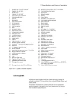
Electrical block diagram
AC.24.126
1.
Inlet/Fuses/Filter
36.
Auxiliary/ACGO light and switch, optional
2.
Transient suppression board
37.
Bottom task light board
3.
AC outlets, optional
38.
Air control valve
4.
Isolation transformer, optional
39.
N2O control valve
5.
AC/DC
40.
O2 bypass valve
6.
Power management board
41.
O2 latching valve
7.
Fan
42.
O2 control flow sensor
8.
Battery
43.
N2O control flow sensor
9.
Carrier board and CPU
44.
Air control flow sensor
10.
USB I/O port
45.
Air pipeline sensor board
11.
USB I/O port
46.
N2O pipeline sensor board
12.
Network I/O port (Ethernet)
47.
Second O2 cylinder transducer
13.
Network I/O port (Ethernet)
48.
O2 pipeline sensor board
14.
Patient monitoring On/Standby
49.
N2O cylinder transducer
15.
Serial I/O port
50.
O2 cylinder transducer
16.
Keypad
51.
Air cylinder transducer
17.
ComWheel
52.
Center top vaporizer light board
18.
Speaker
53.
O2 flow indicator light, optional
19.
LCD and touchscreen
54.
N2O flow indicator light, optional
20.
Anesthesia computer board
55.
Air flow indicator light, optional
21.
Airway module
56.
Left top task light
11 Specifications and theory of operation
2076152-001
11-7
Summary of Contents for Carestation 620
Page 1: ...Carestation 620 650 650c A1 User s Reference Manual Software Revision 01...
Page 12: ...Carestation 620 650 650c A1 x 2076152 001...
Page 58: ...2 24 2076152 001...
Page 98: ...3 40 2076152 001...
Page 102: ...4 4 2076152 001...
Page 128: ...6 12 2076152 001...
Page 150: ...7 22 2076152 001...
Page 182: ...8 32 2076152 001...
Page 196: ...9 14 2076152 001...
Page 246: ...11 44 2076152 001...
Page 268: ...Carestation 620 650 650c A1 User s Reference Manual English 2076152 001 2021 05 Rev S...

