Part Number 88301-01
Rev. H (08/07)
Bently Nevada™ Asset Condition Monitoring
Operation Manual
Accelerometer Interface Module
Page 1: ...Part Number 88301 01 Rev H 08 07 Bently Nevada Asset Condition Monitoring Operation Manual Accelerometer Interface Module ...
Page 2: ... of General Electric Company in the United States and other countries Bently Nevada Keyphasor Proximitor Contact Information The following ways of contacting Bently Nevada are provided for those times when you cannot contact your local representative Mailing Address 1631 Bently Parkway South Minden Nevada USA 89423 USA Telephone 1 775 782 3611 1 800 227 5514 Fax 1 775 215 2873 Internet www ge ener...
Page 3: ...bration Monitoring Part Number AN051 General Electric LM 1600 Gas Generator and Gas Turbine Vibration Monitoring Part Number AN052 General Electric LM 2500 Gas Generator and Gas Turbine Vibration Monitoring Part Number AN053 General Electric LM 5000 Gas Generator and Gas Turbine Vibration Monitoring Part Number AN054 General Electric LM 6000 Gas Turbine Vibration Monitoring Part Number AN055 Produ...
Page 4: ...ield Wiring 8 4 MAINTENANCE 18 4 1 Calibration and Velocity Signal Path Verification 18 4 2 Common Mode Rejection Measurement 23 4 3 Troubleshooting 23 4 3 1 Fault Indication 1 23 4 3 2 Fault Indication 2 24 4 3 3 Fault Indication 3 24 5 ORDERING INFORMATION 26 6 INTERFACE MODULE OPTIONS 28 7 SPECIFICATIONS 29 7 1 Accelerometer Interface Module 29 7 2 Accelerometer Interface Module 30 7 3 Extensio...
Page 5: ... the features of the system Section 2 gives typical receiving inspecting and installation instructions and field wiring and hazardous area installation instructions Section 3 shows how to recalibrate the charge amplifier and verify the velocity signal output This section also contains troubleshooting information Section 4 provides ordering information and Section 5 describes the ordering options f...
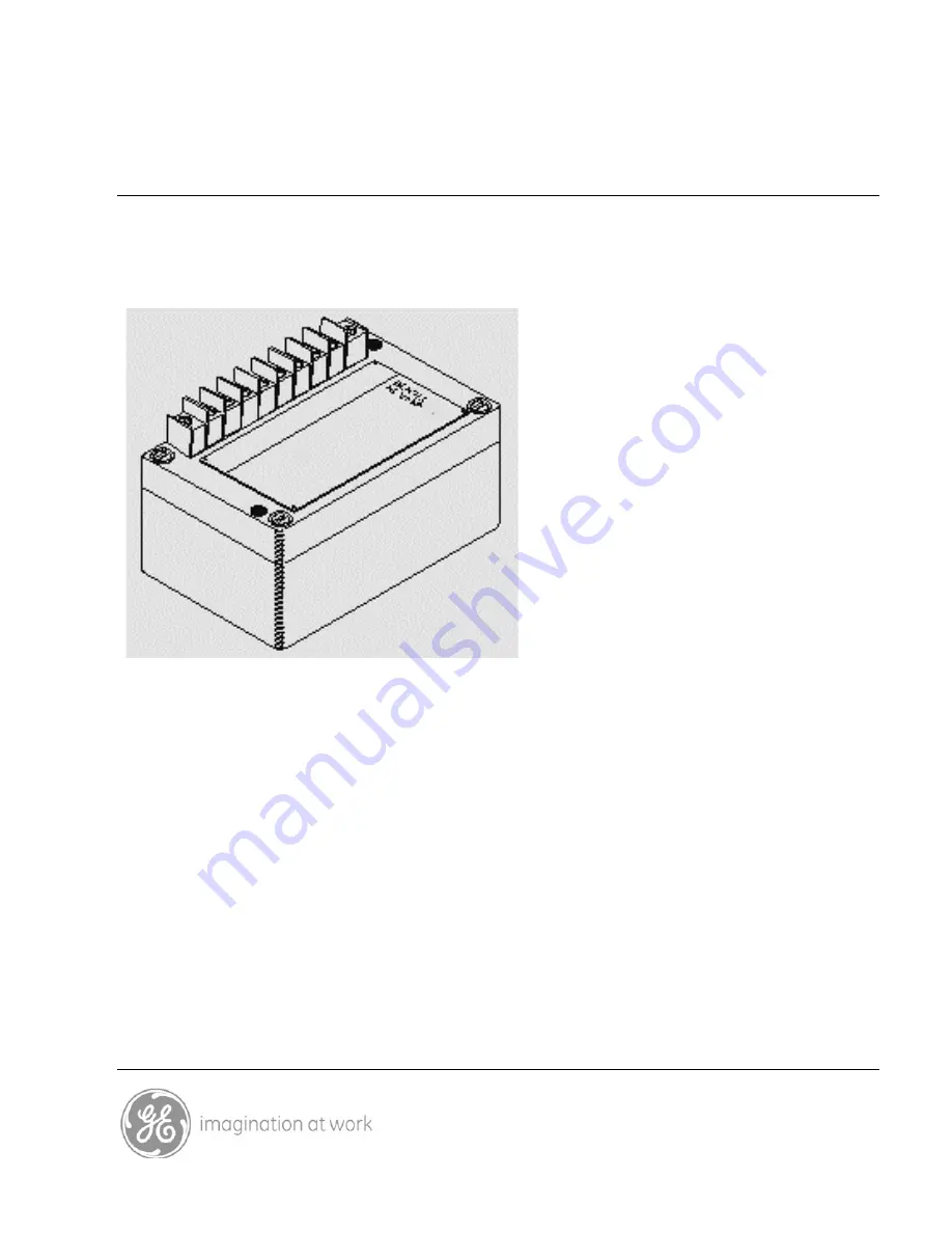
Page 6: ... SYSTEM OVERVIEW The accelerometer based transducer system consists of a high temperature charge coupled accelerometer rugged low noise high temperature extension cable s and the accelerometer interface module as shown below Figure 1 1 Transducer System ...
Page 7: ...ignal to 10 mV g peak 1 02 mV m s2 pk 3 Buffers the acceleration signal so that it can be connected to instrumentation over long cable lengths 4 Bandpass filters the acceleration signal using a 12th order filter with corner frequencies determined by option BB 5 Integrates the filtered acceleration signal to a velocity signal with a sensitivity of 100 mV in s pk 3 94 mV mm s pk 6 Buffers the veloci...
Page 8: ... consideration should be given to the fact that the acceleration signal will contain structural and or structural borne noise that is not related to rotor vibration Most common machine malfunctions originate on the rotor and can be detected as a change in rotor vibration Choose corner frequencies carefully Both the acceleration and velocity signal outputs can be wired as either single ended output...
Page 9: ...lified by the engine manufacturer Accelerometers of this type are typically constructed with a piezoelectric crystal isolated from the accelerometer case so that the accelerometer output is differential Accelerometers used with the 86517 interface module must have a sensitivity of 50 picocoulombes per g or 100 picocoulombes per g and the necessary connector Bently Nevada offers a 50 pC g charge co...
Page 10: ...face Module Mount the interface module in an enclosure that protects it from mechanical damage contamination the weather and which isolates the interface module Bently Nevada part number 80808 01 and 02 are stainless steel weatherproof housings with a built in insulated mounting plate Housing drawings are in the appendix For installations in hazardous areas requiring agency approvals the housing m...
Page 11: ...case of steam injection turbines away from any steam manifolds Secure the extension cable at frequent intervals to prevent excessive vibration Cable vibration can induce charge on the conductors which appear as noise to the input of the charge amplifier Figure 2 1 Typical Installation CAUTION To prevent interference of machinery monitoring radio transmitters should not be operated used within 6 fe...
Page 12: ...ll system to meet certification requirements When specifying an agency certified system you should verify that both the interface module and accelerometer have the appropriate hazardous area certification The Bently Nevada accelerometer part number 45357 01 is certified for use in Class I Divisions 1 and 2 by the Canadian Standards Association When installing a CENELEC approved system you must att...
Page 13: ...on 1 and Zone 1 hazardous areas Note that to meet the requirements of the Zone 1 IIB approval from SIRA certification services a tag should be attached to the power common signal cable at the safety barrier When the interface module is ordered with the CENELEC Zone 1 approval the unit is shipped with the tag attached to the ground strap on the terminal block The tag is mylar with an adhesive back ...
Page 14: ...Accelerometer Interface Module Operation Manual 10 Figure 2 2 Field Wiring to 3300 95 Monitor without Barriers Notes on following page ...
Page 15: ...mmon Velocity and Velocity wiring recommendation two twisted pairs of stranded 18 to 22 AWG wire with insulating sheath and 100 shield coverage 1000 feet 305 metres maximum Use Bently Nevada part number 02101200 or equivalent 5 Interface module to monitor Accel wiring recommendation stranded twisted pair 18 to 22 AWG insulating sheath and 100 shield coverage 1000 feet 305 metres maximum Shielding ...
Page 16: ...Accelerometer Interface Module Operation Manual 12 Figure 2 3 Field Wiring to 3300 Monitor without Barriers Notes on following page ...
Page 17: ...G stranded three conductor wire with insulating sheath and 100 shield coverage 1000 feet 305 metres maximum 18 AWG Belden 83336 or 22 AWG Belden 83334 can be used Shielding 4 At the interface module the shield connects to the terminal marked CASE SHIELD Note that a jumper shunt is installed between the terminal block mounting screw and the CASE SHIELD terminal 6 The shield terminates at signal com...
Page 18: ...Accelerometer Interface Module Operation Manual 14 Figure 2 4 Field Wiring Interface Module to 3300 95 Monitor with Barriers Notes on following page ...
Page 19: ...ity wire from the monitor to barrier ground but not to the interface module The shield connects to the CASE SHIELD terminal at the interface module The maximum length is 800 feet 244 metres between the interface module and the barrier and 1000 feet 305 metres between the interface module and the monitor Use Bently Nevada part number 02101200 or equivalent 5 Interface module to monitor acceleration...
Page 20: ...le point earth ground NOTE When external barriers are used the jumper between signal common and rack chassis on the 3300 Power Input Module at the rear of the 3300 rack must be removed See the 3300 System Installation Instructions document part number 80172 01 Figure 2 5 Field Wiring Interface Module to 3300 Monitor with External Barriers Notes on the following page ...
Page 21: ...ath and 100 shield coverage The Velocity output at the interface module is not connected The maximum cable length between the monitor and the interface module is 1000 feet 305 metres and the maximum length between the interface module and the barrier is 800 feet 244 metres 18 AWG Belden 83336 or 22 AWG Belden 83334 can be used Shielding 5 Barrier ground is the single point earth ground The shields...
Page 22: ... Ideally the interface module should be calibrated with an accelerometer a shake table and a high quality reference accelerometer Unfortunately this is not usually practical This procedure uses a voltage signal from a function generator and a capacitor to produce a charge input to the interface module The technique works well provided that you are in a low EMI environment make good connections hav...
Page 23: ... generator to a null output level and measure the acceleration signal with the multimeter If the reading is more than a few millivolts rms then the test setup is probably injecting power line noise into the charge amplifier You need to lower the noise level before continuing Try reducing lead lengths and changing lead routing 3 Adjust the function generator to output a 0 3535 Vrms sine wave at 100...
Page 24: ...the lid and fold it back 7 Adjust the potentiometer until the multimeter reads 0 3535 7 0 Vrms Close and tighten the lid and verify that the multimeter still reads 0 3535 Vrms If it does not then repeat steps 6 and 7 Note that when the lid is open the circuitry is unshielded and the charge amp can pick up noise ...
Page 25: ... and B not connected Verify that the multimeter still reads 0 3535 Vrms 7 0 mVrms If it does not then check your test setup as in step 2 and then repeat this step If the test is not passed then replace the interface module To verify the velocity signal path continue with step 9 on the following page ...
Page 26: ...r corner frequencies and accelerometer charge sensitivity as shown in the table below Corner frequency Function Generator Setting High Pass Corner Low Pass Corner Frequency Amplitude Hz Hz Hz mVrms 25 350 93 5 53 8 50 pC transducer 100 560 236 6 136 2 50 pC transducer 40 300 109 5 126 0 100 pC transducer 11 Measure the VELOCITY output with the multimeter It should read 0 3535 Vrms 18 0 mVrms If it...
Page 27: ...roubleshooting procedure will help you interpret a fault indication and isolate faults in an installed transducer system Before beginning make sure the system has been installed correctly When a malfunction occurs locate the fault indication check the probable causes for the fault indication and follow the procedure to isolate and correct the problem 4 3 1 Fault Indication 1 The voltage between th...
Page 28: ... third option configurator of the part number which is shown on the interface module identification plate Probable Cause Fault in the Velocity signal field wiring Faulty power supply Faulty interface module Isolation and Correction Verify that fault condition 1 does not exist Disconnect the VELOCITY and VELOCITY wires from the interface module and measure the voltage between VELOCITY and COM If th...
Page 29: ...e signal path Check the accelerometer mounting Check the extension cable for damage and make sure it is well secured at regular intervals to prevent cable vibration Verify that the interface module is isolated from earth and that the shields are wired correctly If the problem still exists after completing the troubleshooting procedure and you are sure the spiking is not a real vibration signal the...
Page 30: ...0 Hz low pass corner 02 100 Hz high pass corner 560 Hz low pass corner 03 40 Hz high pass corner 300 Hz low pass corner C DC Signal Bias Voltage 01 10 Vdc No other option available D Agency Approval 00 Not Required 01 Canadian Standards Association 02 CENELEC SIRA Extension Cable Softline Cable 45358 07 7 Metre 45358 09 9 Metre Hardline Cable 83387 054 54 inch 065 65 inch 096 96 inch 100 100 inch ...
Page 31: ... procured separately Accessories 0 01 microfarad capacitor BNC P N 00448308 Connector for connection of unterminated extension cables to interface module Requires potting BNC P N 00591075 Recommended Spare Parts One spare interface module extension cable and accelerometer should be kept on hand If five or more transducer systems are installed then one spare of each part is suggested in a ratio of ...
Page 32: ...required if the option is changed Option BB Filter Corner Frequency This option determines the filter corner frequencies and cannot be changed without changing components on the Filter PWA Option CC DC Signal Bias Voltage Only Option CC 01 is available This sets the dc bias voltage at 10 Vdc Soldered link W2 on the Filter PWA is not installed Option DD Agency Approval The 86517 interface module is...
Page 33: ... pC g pk sensitivity and 100 000 pC peak for accelerometers with 100 pC g pk sensitivity ACCELERATION OUTPUT Sensitivity 10 mV g pk 1 02 mV m s2 pk balanced output 50 ohm nominal output impedance Dynamic Range 750 gs 7350 m s2 without barriers typical 500 gs 4902 m s2 with barriers typical Frequency Response The low frequency response is controlled by the charge amplifier The 3 dB corner is at 4 7...
Page 34: ...High and low pass corner frequencies are ordered as pairs the following pairs can be ordered High Pass Corner Low Pass Corner 25 Hz 350 Hz 40 Hz 300 Hz 100 Hz 560 Hz The high and low pass filters are 6th order with 36 dB octave rolloff and have a butterworth response Attenuation at the corner frequency is 3 dB 0 5 dB ENVIRONMENTAL Operating Temperature 32 F to 158 F 0 C to 70 C Storage Temperature...
Page 35: ...3112 8 3P Cable Twisted shielded pair with low noise construction Protected by convoluted teflon tubing overall and the rear of the connectors are potted Operating Temperatures Cable 65 F to 400 F 54 C to 204 C Accelerometer mating connector 65 F to 392 F 54 C to 200 C Interface module mating connector 50 F to 200 F 45 C to 93 C HARDLINE CABLE Accelerometer Mating Connector Mates to MS 3100R 10SL ...
Page 36: ...tor 65 F to 800 F 54 C to 427 C Disconnect interface mating connector 65 F to 800 F 54 C to 427 C 7 4 Accelerometer P N 45357 01 Sensitivity 50 pC g 5 Mounting 4 holes at the corners of a square with 1 188 inch 30 17 mm sides Suitable for mounting with 0 25 inch or 6 mm bolts Connector MS3100R 10SL 4P Weight 15 Ounces 425 grams nominal ...
Page 37: ...Section 8 APPENDIX Drawings 33 8 APPENDIX Drawings ...
Page 38: ...l Base Overall Mounting BL x BW L x W G x H Small SST 12 00 in x 12 00 in 13 50 in x 12 94 in 12 75 in x 10 00 in Enclosure 304 8mm x 304 8mm 342 9mm x 328 7mm 323 8mm x 254mm Large SST 18 00 in x 18 00 in 19 50 in x 18 94 in 18 75 in x 16 00 in Enclosure 457 2mm x 457 2mm 495 3mm x 481 1mm 476 2mm x 406 4mm ...
Page 39: ...Section 8 APPENDIX Drawings 35 Figure A 2 Interfaule Assembly ...