


[36] Mains failure
inverse
Activates
. Mains failure
inverse is active in the Logic .0. situation.
[41] Latched Precise
Stop inverse
Sends a latched stop signal when the
precise stop function is activated in
. The Latched
Precise stop inverse function is available
for terminals 18 or 19.
[55] DigiPot
Increase
INCREASE signal to the Digital Potenti-
ometer function described in parameter
group F-9#
[56] DigiPot
Decrease
DECREASE signal to the Digital Potenti-
ometer function described in parameter
group F-9#
[57] DigiPot Clear
Clears the Digital Potentiometer reference
described in parameter group F-9#
[60] Counter A
(Terminal 29 or 33 only) Input for
increment counting in the LC counter.
[61] Counter A
(Terminal 29 or 33 only) Input for
decrement counting in the LC counter.
[62] Reset Counter
A
Input for reset of counter A.
[63] Counter B
(Terminal 29 or 33 only) Input for
increment counting in the LC counter.
[64] Counter B
(Terminal 29 or 33 only) Input for
decrement counting in the LC counter.
[65] Reset Counter
B
Input for reset of counter B.
[70] Mech. Brake
Feedback
Brake feedback for hoisting applications
[71] Mech. Brake
Feedback inv.
Inverted brake feedback for hoisting
applications
[80] PTC Card 1
All Digital Inputs can be set to PTC Card 1
[80]. However, only one Digital Input must
be set to this choice.
E-00 Digital I/O Mode
Option:
Function:
Digital inputs and programmed digital outputs are
pre-programmable for operation either in PNP or NPN
systems.
[0]
*
PNP Action on positive directional pulses
(↕)
. PNP systems
are pulled down to GND.
[1]
NPN Action on negative directional pulses
(↕)
. NPN
systems are pulled up to + 24 V, internally in the
frequency converter.
NOTE
Once this parameter has been changed, it must be
activated by performing a power cycle.
E-01 Terminal 18 Digital Input
Option: Function:
The options are the same as those listed for parameter
group E-0#.
E-02 Terminal 19 Digital Input
Option: Function:
The options are the same as those listed for parameter
group E-0#.
E-03 Terminal 27 Digital Input
Option: Function:
The options are the same as those listed for parameter
group E-0#.
E-04 Terminal 29 Digital Input
Option: Function:
The options are the same as those listed for parameter
group E-0#.
E-05 Terminal 32 Digital Input
Option: Function:
The options are the same as those listed for parameter
group E-0#.
E-06 Terminal 33 Digital Input
Option: Function:
The options are the same as those listed for parameter
group E-0#.
E-07 Terminal 37 Safe Stop
Option:
Function:
[1]
*
Safe Stop
Alarm
Coasts frequency converter when safe
stop is activated. Manual reset from
keypad, digital input or Network.
[3]
Safe Stop
Warning
Coasts frequency converter when safe
stop is activated (term 37 off). When safe
stop circuit is reestablished, the frequency
converter will continue without manual
reset.
NOTE
When Auto Reset/ Warning is selected the frequency
converter opens up for automatic restart.
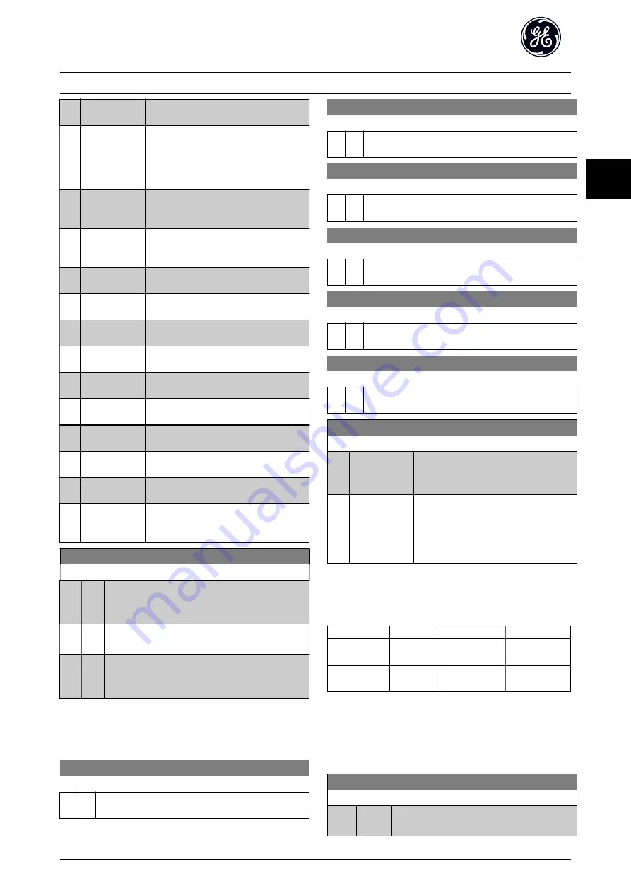
Function
No.
PTC
Relay
Safe Stop
Alarm
[1]*
-
Safe Stop [A68]
Safe Stop
Warning
[3]
-
Safe Stop [W68]
Table 3.10 Overview of Functions, Alarms and Warnings
3.4.2 E-1# Additional Accel/Decel Ramps
Parameters to configure the Accel/Decel Ramps 2, 3, and 4.
E-10 Accel Time 2
Range:
Function:
3.00
s
*
[0.01 -
3600 s]
Enter the accel time from 0 RPM to the rated
motor speed n
s
. Choose a accel time such that
Parameter Descriptions
AF-650 GP Programming Guide
DET-618C
45
3
3


