GE Multilin
F35 Multiple Feeder Protection System
3-7
3 HARDWARE
3.1 DESCRIPTION
3
The 4.0x release of the F35 relay includes new hardware modules.The new CPU modules are specified with codes
9E and higher. The new CT/VT modules are specified with the codes 8F and higher.
The new CT/VT modules can only be used with new CPUs; similarly, old CT/VT modules can only be used with old
CPUs. To prevent hardware mismatches, the new modules have blue labels and a warning sticker stating
“Attn.:
Ensure CPU and DSP module label colors are the same!”
. In the event that there is a mismatch between the
CPU and CT/VT module, the relay will not function and a
DSP ERROR
or
HARDWARE MISMATCH
error will be dis-
played.
All other input and output modules are compatible with the new hardware. Firmware versions 4.0x and higher are
only compatible with the new hardware modules. Previous versions of the firmware (3.4x and earlier) are only com-
patible with the older hardware modules.
3.1.3 REAR TERMINAL LAYOUT
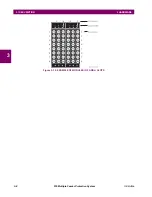
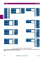
Figure 3–9: REAR TERMINAL VIEW
Do not touch any rear terminals while the relay is energized!
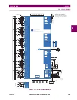
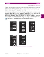
The relay follows a convention with respect to terminal number assignments which are three characters long assigned in
order by module slot position, row number, and column letter. Two-slot wide modules take their slot designation from the
first slot position (nearest to CPU module) which is indicated by an arrow marker on the terminal block. See the following
figure for an example of rear terminal assignments.
NOTE
X
W
V
U
T
S
P
N
M
L
K
J
H
D
G
F
B
R
8
4
7
3
6
2
5
1
b
8
4
7
3
6
2
5
1
a
a
b
c
a
b
c
a
b
c
a
b
c
4
3
2
1
b
4
3
2
1
a
IN
OUT
Tx1
Tx2
Rx2
Rx1
CH1
Tx
CH2
Rx
CH1
CH2
®
®
Technical Support:
Tel: (905) 294-6222
Fax: (905) 201-2098
Model:
Mods:
Wiring Diagram:
Inst. Manual:
Serial Number:
Firmware:
Mfg. Date:
F35D00HCHF8AH6AM6BP8BX7A
000
ZZZZZZ
D
MAZB98000029
D
1999/01/05
Control Power:
Contact Inputs:
Contact Outputs:
88-300V DC @ 35W / 77-265V AC @ 35VA
300V DC Max 10mA
Standard Pilot Duty / 250V AC 7.5A
360V A Resistive / 125V DC Break
4A @ L/R = 40mS / 300W
RATINGS:
F35
Multiple Feeder Management Relay
Made in
Canada
- M A A B 9 7 0 0 0 0 9 9 -
http://www.GEIndustrial.com/Multilin
GE Multilin
Optional
Ethernet
switch
Optional
direct
input/output
module
CPU module
(Ethernet not
available when
ordered with
Ethernet switch)
Optional
contact
input/output
module
CT/VT
module
Power
supply
module
Tx1
Tx2
Rx1
Rx2
Tx1
Tx2
832766A3.CDR
Optional
CT/VT or
contact
input/output
module
Optional
contact
input/output
module
WARNING
Summary of Contents for F35
Page 2: ......
Page 4: ......
Page 296: ...5 174 F35 Multiple Feeder Protection System GE Multilin 5 9 TESTING 5 SETTINGS 5 ...
Page 328: ...7 8 F35 Multiple Feeder Protection System GE Multilin 7 2 TARGETS 7 COMMANDS AND TARGETS 7 ...
Page 350: ...A 16 F35 Multiple Feeder Protection System GE Multilin A 1 PARAMETER LIST APPENDIXA A ...
Page 422: ...B 72 F35 Multiple Feeder Protection System GE Multilin B 4 MEMORY MAPPING APPENDIXB B ...
Page 472: ...E 12 F35 Multiple Feeder Protection System GE Multilin E 2 DNP POINT LISTS APPENDIXE E ...


