


GE Multilin
F60 Feeder Protection System
3-31
3 HARDWARE
3.2 WIRING
3
3.2.10 IRIG-B
IRIG-B is a standard time code format that allows stamping of events to be synchronized among connected devices. The
IRIG-B code allows time accuracies of up to 100 ns. Using the IRIG-B input, the F60 operates an internal oscillator with 1
µs resolution and accuracy. The IRIG time code formats are serial, pulse width-modulated codes that can be either DC
level shifted or amplitude modulated (AM). The GE MultiSync 100 1588 GPS Clock as well as third-party equipment are
available for generating the IRIG-B signal; this equipment can use a global positioning system (GPS) satellite system to
obtain the time reference so that devices at different geographic locations can be synchronized.
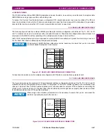
Figure 3–30: OPTIONS FOR THE IRIG-B CONNECTION
Using an amplitude modulated receiver causes errors up to 1 ms in event time-stamping.
The F60 is intended for use with external clocks that set the IRIG-B control bits according to IEEE Std C37.118.1-
2011. When used with a source that sets the IRIG-B control bits according to IEEE Std 1344-1995, the source must
have the sign of its local time offset setting reversed, and if daylight savings time (DST) is used, the source's DST
start and DST stop date settings must be interchanged.
UR-series device
BNC (in)
Receiver
RG58/59 coaxial cable
GPS satellite system
GPS connection
IRIG-B (–)
4A
+
827756A8.CDR
IRIG-B
time code generator
(DC-shift or
amplitude modulated
signal can be used)
4B IRIG-B (+)
UR-series device
BNC (in)
Receiver
Twisted-pair cable
GPS satellite system
GPS connection
IRIG-B (–)
4A
+
IRIG-B
time code generator
(DC-shift or
amplitude modulated
signal can be used)
4B IRIG-B (+)
NOTE
Summary of Contents for F60
Page 10: ...x F60 Feeder Protection System GE Multilin TABLE OF CONTENTS ...
Page 30: ...1 20 F60 Feeder Protection System GE Multilin 1 5 USING THE RELAY 1 GETTING STARTED 1 ...
Page 138: ...4 28 F60 Feeder Protection System GE Multilin 4 2 FACEPLATE INTERFACE 4 HUMAN INTERFACES 4 ...
Page 454: ...5 316 F60 Feeder Protection System GE Multilin 5 10 TESTING 5 SETTINGS 5 ...
Page 500: ...7 14 F60 Feeder Protection System GE Multilin 7 1 COMMANDS 7 COMMANDS AND TARGETS 7 ...
Page 508: ...8 8 F60 Feeder Protection System GE Multilin 8 2 FAULT LOCATOR 8 THEORY OF OPERATION 8 ...
Page 522: ...10 12 F60 Feeder Protection System GE Multilin 10 6 DISPOSAL 10 MAINTENANCE 10 ...
Page 660: ...B 116 F60 Feeder Protection System GE Multilin B 4 MEMORY MAPPING APPENDIX B B ...
Page 706: ...E 10 F60 Feeder Protection System GE Multilin E 1 IEC 60870 5 104 APPENDIX E E ...
Page 718: ...F 12 F60 Feeder Protection System GE Multilin F 2 DNP POINT LISTS APPENDIX F F ...
Page 728: ...H 8 F60 Feeder Protection System GE Multilin H 2 ABBREVIATIONS APPENDIX H H Z Impedance Zone ...
Page 730: ...H 10 F60 Feeder Protection System GE Multilin H 3 WARRANTY APPENDIX H H ...


