


3-26
F60 Feeder Protection System
GE Multilin
3.2 WIRING
3 HARDWARE
3
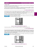
Figure 3–24: ACTIVE IMPEDANCE CONTACT INPUT V-I CHARACTERISTIC
3.2.7 TRANSDUCER INPUTS/OUTPUTS
Transducer input modules can receive input signals from external DCmA output transducers (DCmA In) or resistance tem-
perature detectors (RTDs). Hardware and software are provided to receive signals from these external transducers and
convert these signals into a digital format for use as required.
Transducer output modules provide DC current outputs in several standard DCmA ranges. Software is provided to config-
ure virtually any analog quantity used in the relay to drive the analog outputs.
Every transducer input/output module has a total of 24 terminal connections. These connections are arranged as three ter-
minals per row with a total of eight rows. A given row can be used for either inputs or outputs, with terminals in column "a"
having positive polarity and terminals in column "c" having negative polarity. Since an entire row is used for a single input/
output channel, the name of the channel is assigned using the module slot position and row number.
Each module also requires that a connection from an external ground bus be made to terminal 8b. The current outputs
require a twisted-pair shielded cable, where the shield is grounded at one end only. The following figure illustrates the trans-
ducer module types (5A, 5C, 5D, 5E, and 5F) and channel arrangements that can be ordered for the relay.
Wherever a tilde “~” symbol appears, substitute with the slot position of the module.
NOTE
Summary of Contents for F60
Page 10: ...x F60 Feeder Protection System GE Multilin TABLE OF CONTENTS ...
Page 30: ...1 20 F60 Feeder Protection System GE Multilin 1 5 USING THE RELAY 1 GETTING STARTED 1 ...
Page 138: ...4 28 F60 Feeder Protection System GE Multilin 4 2 FACEPLATE INTERFACE 4 HUMAN INTERFACES 4 ...
Page 454: ...5 316 F60 Feeder Protection System GE Multilin 5 10 TESTING 5 SETTINGS 5 ...
Page 500: ...7 14 F60 Feeder Protection System GE Multilin 7 1 COMMANDS 7 COMMANDS AND TARGETS 7 ...
Page 508: ...8 8 F60 Feeder Protection System GE Multilin 8 2 FAULT LOCATOR 8 THEORY OF OPERATION 8 ...
Page 522: ...10 12 F60 Feeder Protection System GE Multilin 10 6 DISPOSAL 10 MAINTENANCE 10 ...
Page 660: ...B 116 F60 Feeder Protection System GE Multilin B 4 MEMORY MAPPING APPENDIX B B ...
Page 706: ...E 10 F60 Feeder Protection System GE Multilin E 1 IEC 60870 5 104 APPENDIX E E ...
Page 718: ...F 12 F60 Feeder Protection System GE Multilin F 2 DNP POINT LISTS APPENDIX F F ...
Page 728: ...H 8 F60 Feeder Protection System GE Multilin H 2 ABBREVIATIONS APPENDIX H H Z Impedance Zone ...
Page 730: ...H 10 F60 Feeder Protection System GE Multilin H 3 WARRANTY APPENDIX H H ...


