


5-272
F60 Feeder Protection System
GE Multilin
5.7 CONTROL ELEMENTS
5 SETTINGS
5
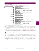
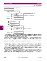
e) BREAKER RESTRIKE
PATH: SETTINGS
CONTROL ELEMENTS
MONITORING ELEMENTS
BREAKER RESTRIKE 1
One breaker restrike element is provided in the F60.
According to IEEE standard C37.100:
IEEE Standard Definitions for Power Switchgear
, restrike is defined as “a resumption
of current between the contacts of a switching device during an opening operation after an interval of zero current of
¼ cycle at normal frequency or longer”.
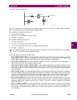
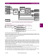
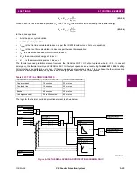
Figure 5–126: TYPICAL RESTRIKE WAVEFORM AND DETECTION FLAG
The breaker restrike algorithm responds to a successful interruption of the phase current following a declaration of capaci-
tor bank offline as per the breaker pole indication. If a high-frequency or system frequency current with a magnitude greater
than the threshold is resumed at least ¼ of a cycle later than the phase current interruption, then a breaker restrike condi-
BREAKER RESTRIKE 1
BREAKER RESTRIKE 1
FUNCTION: Disabled
Range: Disabled, Enabled
MESSAGE
BKR RSTR 1 BLOCK:
Off
Range: FlexLogic operand
MESSAGE
BREAKER RESTRIKE 1
SOURCE: SRC 1
Range: SRC 1, SRC 2, SRC 3, SRC 4
MESSAGE
BREAKER RESTRIKE 1
PICKUP: 0.500 pu
Range: 0.10 to 2.00 pu in steps of 0.01
MESSAGE
BREAKER RESTRIKE 1
RESET DELAY: 0.100 s
Range: 0.000 to 65.535 s in steps of 0.001
MESSAGE
BREAKER RESTRIKE 1
HF DETECT: Enabled
Range: Disabled, Enabled
MESSAGE
BKR RSTR 1 BKR OPEN:
Off
Range: FlexLogic operand
MESSAGE
BKR RSTR 1 OPEN CMD:
Off
Range: FlexLogic operand
MESSAGE
BKR RSTR 1 CLS CMD:
Off
Range: FlexLogic operand
MESSAGE
BREAKER RESTRIKE 1
TARGET: Self-reset
Range: Self-reset, Latched, Disabled
MESSAGE
BREAKER RESTRIKE 1
EVENTS: Disabled
Range: Disabled, Enabled
0
2
4
6
8
10
–2
–4
–6
–8
–10
0.01
0.02
0.03
0.05
time (ms)
curr
ent
(amps)
OPERATE
834764A1.CDR
Summary of Contents for F60
Page 10: ...x F60 Feeder Protection System GE Multilin TABLE OF CONTENTS ...
Page 30: ...1 20 F60 Feeder Protection System GE Multilin 1 5 USING THE RELAY 1 GETTING STARTED 1 ...
Page 138: ...4 28 F60 Feeder Protection System GE Multilin 4 2 FACEPLATE INTERFACE 4 HUMAN INTERFACES 4 ...
Page 454: ...5 316 F60 Feeder Protection System GE Multilin 5 10 TESTING 5 SETTINGS 5 ...
Page 500: ...7 14 F60 Feeder Protection System GE Multilin 7 1 COMMANDS 7 COMMANDS AND TARGETS 7 ...
Page 508: ...8 8 F60 Feeder Protection System GE Multilin 8 2 FAULT LOCATOR 8 THEORY OF OPERATION 8 ...
Page 522: ...10 12 F60 Feeder Protection System GE Multilin 10 6 DISPOSAL 10 MAINTENANCE 10 ...
Page 660: ...B 116 F60 Feeder Protection System GE Multilin B 4 MEMORY MAPPING APPENDIX B B ...
Page 706: ...E 10 F60 Feeder Protection System GE Multilin E 1 IEC 60870 5 104 APPENDIX E E ...
Page 718: ...F 12 F60 Feeder Protection System GE Multilin F 2 DNP POINT LISTS APPENDIX F F ...
Page 728: ...H 8 F60 Feeder Protection System GE Multilin H 2 ABBREVIATIONS APPENDIX H H Z Impedance Zone ...
Page 730: ...H 10 F60 Feeder Protection System GE Multilin H 3 WARRANTY APPENDIX H H ...


