5-262
F60 Feeder Protection System
GE Multilin
5.7 CONTROL ELEMENTS
5 SETTINGS
5
•
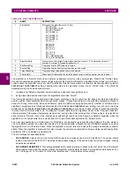
HI-Z LOSS OF LOAD THRESHOLD
: Establishes the loss of load level used as an indication of a downed conductor. A
Loss of Load flag is set if the Hi-Z algorithms detect a percentage drop in phase current between two successive two-
cycle RMS values that equals or exceeds the Loss of Load Threshold. The amount the phase current must decrease
between successive two-cycle RMS values is based on this setting times the recent average phase current level. The
range is 5 to 100%; 5% being the most sensitive.
•
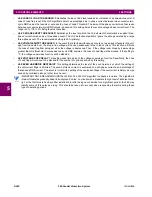
HI-Z 3-PHASE EVENT THRESHOLD
: Establishes the level at which the Hi-Z element characterizes a sudden three-
phase current increase as a three-phase event. The Hi-Z detection algorithms ignore the data generated by a large
three-phase event. The recommended setting is 25 A (
primary
).
•
HI-Z VOLTAGE SUPV THRESHOLD
: In the event that a fault simultaneously occurs on two adjacent feeders (line volt-
age from the same bus), the drop in line voltage will cause a subsequent drop in load current. This function will block
the Loss of Load flag from being set while the voltage is depressed. Thus, if the voltage level drops by a percentage
greater than this threshold in successive two-cycle RMS samples, the Loss of Load flag will be blocked. If the setting is
“0”, the voltage supervision function will be disabled.
•
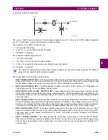
HI-Z VOLTAGE SUPV DELAY
: This setting adds time delay to the voltage supervision function. Specifically, the Loss
of Load flag will continue to be blocked for the number of cycles specified by this setting.
•
HI-Z EVEN HARMONIC RESTRAINT
: This setting determines the level of the even harmonic at which the setting of
the overcurrent flags is inhibited. The even harmonic content is evaluated on each phase current as a percentage of
that phase's RMS current. The intent is to inhibit the setting of the overcurrent flags if the overcurrent is simply a surge
caused by cold-load pickup or other inrush event.
IMPORTANT NOTE REGARDING INSTALLATION: The F60 Hi-Z algorithm is adaptive in nature. The algorithm’s
internal thresholds gradually adapt to background “noise” on circuits with a moderate to high level of transient activ-
ity. For the first three to five days after installation (or after being out-of-service for a significant period), the F60 may
identify some of this noise as arcing. This should be taken into account when responding to alarms during these
type of operating periods.
NOTE
Summary of Contents for F60
Page 10: ...x F60 Feeder Protection System GE Multilin TABLE OF CONTENTS ...
Page 30: ...1 20 F60 Feeder Protection System GE Multilin 1 5 USING THE RELAY 1 GETTING STARTED 1 ...
Page 138: ...4 28 F60 Feeder Protection System GE Multilin 4 2 FACEPLATE INTERFACE 4 HUMAN INTERFACES 4 ...
Page 454: ...5 316 F60 Feeder Protection System GE Multilin 5 10 TESTING 5 SETTINGS 5 ...
Page 500: ...7 14 F60 Feeder Protection System GE Multilin 7 1 COMMANDS 7 COMMANDS AND TARGETS 7 ...
Page 508: ...8 8 F60 Feeder Protection System GE Multilin 8 2 FAULT LOCATOR 8 THEORY OF OPERATION 8 ...
Page 522: ...10 12 F60 Feeder Protection System GE Multilin 10 6 DISPOSAL 10 MAINTENANCE 10 ...
Page 660: ...B 116 F60 Feeder Protection System GE Multilin B 4 MEMORY MAPPING APPENDIX B B ...
Page 706: ...E 10 F60 Feeder Protection System GE Multilin E 1 IEC 60870 5 104 APPENDIX E E ...
Page 718: ...F 12 F60 Feeder Protection System GE Multilin F 2 DNP POINT LISTS APPENDIX F F ...
Page 728: ...H 8 F60 Feeder Protection System GE Multilin H 2 ABBREVIATIONS APPENDIX H H Z Impedance Zone ...
Page 730: ...H 10 F60 Feeder Protection System GE Multilin H 3 WARRANTY APPENDIX H H ...


