


5-228
F60 Feeder Protection System
GE Multilin
5.7 CONTROL ELEMENTS
5 SETTINGS
5
5.7CONTROL ELEMENTS
5.7.1 OVERVIEW
Control elements are generally used for control rather than protection. See the
Introduction to Elements
section at the
beginning of this chapter for further information.
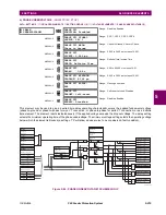
5.7.2 TRIP BUS
PATH: SETTINGS
CONTROL ELEMENTS
TRIP BUS
TRIP BUS 1(6)
The trip bus element allows aggregating outputs of protection and control elements without using FlexLogic and assigning
them a simple and effective manner. Each trip bus can be assigned for either trip or alarm actions. Simple trip conditioning
such as latch, delay, and seal-in delay are available.
The easiest way to assign element outputs to a trip bus is through the EnerVista UR Setup software A protection summary
is displayed by navigating to a specific protection or control protection element and checking the desired bus box. Once the
desired element is selected for a specific bus, a list of element operate-type operands are displayed and can be assigned
to a trip bus. If more than one operate-type operand is required, it may be assigned directly from the trip bus menu.
TRIP BUS 1
TRIP BUS 1
FUNCTION: Disabled
Range: Enabled, Disabled
MESSAGE
TRIP BUS 1 BLOCK:
Off
Range: FlexLogic operand
MESSAGE
TRIP BUS 1 PICKUP
DELAY: 0.00
s
Range: 0.00 to 600.00 s in steps of 0.01
MESSAGE
TRIP BUS 1 RESET
DELAY: 0.00
s
Range: 0.00 to 600.00 s in steps of 0.01
MESSAGE
TRIP BUS 1 INPUT 1:
Off
Range: FlexLogic operand
MESSAGE
TRIP BUS 1 INPUT 2:
Off
Range: FlexLogic operand
↓
MESSAGE
TRIP BUS 1 INPUT 16:
Off
Range: FlexLogic operand
MESSAGE
TRIP BUS 1
LATCHING: Disabled
Range: Enabled, Disabled
MESSAGE
TRIP BUS 1 RESET:
Off
Range: FlexLogic operand
MESSAGE
TRIP BUS 1 TARGET:
Self-reset
Range: Self-reset, Latched, Disabled
MESSAGE
TRIP BUS 1
EVENTS: Disabled
Range: Enabled, Disabled
Summary of Contents for F60
Page 10: ...x F60 Feeder Protection System GE Multilin TABLE OF CONTENTS ...
Page 30: ...1 20 F60 Feeder Protection System GE Multilin 1 5 USING THE RELAY 1 GETTING STARTED 1 ...
Page 138: ...4 28 F60 Feeder Protection System GE Multilin 4 2 FACEPLATE INTERFACE 4 HUMAN INTERFACES 4 ...
Page 454: ...5 316 F60 Feeder Protection System GE Multilin 5 10 TESTING 5 SETTINGS 5 ...
Page 500: ...7 14 F60 Feeder Protection System GE Multilin 7 1 COMMANDS 7 COMMANDS AND TARGETS 7 ...
Page 508: ...8 8 F60 Feeder Protection System GE Multilin 8 2 FAULT LOCATOR 8 THEORY OF OPERATION 8 ...
Page 522: ...10 12 F60 Feeder Protection System GE Multilin 10 6 DISPOSAL 10 MAINTENANCE 10 ...
Page 660: ...B 116 F60 Feeder Protection System GE Multilin B 4 MEMORY MAPPING APPENDIX B B ...
Page 706: ...E 10 F60 Feeder Protection System GE Multilin E 1 IEC 60870 5 104 APPENDIX E E ...
Page 718: ...F 12 F60 Feeder Protection System GE Multilin F 2 DNP POINT LISTS APPENDIX F F ...
Page 728: ...H 8 F60 Feeder Protection System GE Multilin H 2 ABBREVIATIONS APPENDIX H H Z Impedance Zone ...
Page 730: ...H 10 F60 Feeder Protection System GE Multilin H 3 WARRANTY APPENDIX H H ...


