


GE Multilin
F60 Feeder Protection System
5-179
5 SETTINGS
5.6 GROUPED ELEMENTS
5
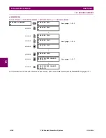
e) PHASE DIRECTIONAL OVERCURRENT
(ANSI 67P, IEC PDOC/PTOC)
PATH: SETTINGS
GROUPED ELEMENTS
SETTING GROUP 1(6)
PHASE CURRENT
PHASE DIRECTIONAL 1(2)
The TARGET setting is not user-selectable and forced to "Disabled". If Targets are required from directional
elements, it can be achieved by assigning directional element output to a digital element, where targets
selection can be used as required.
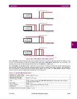
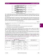
The phase directional elements (one for each of phases A, B, and C) determine the phase current flow direction for steady
state and fault conditions and can be used to control the operation of the phase overcurrent elements via the
BLOCK
inputs
of these elements.
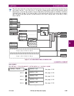
Figure 5–72: PHASE A DIRECTIONAL POLARIZATION
PHASE
DIRECTIONAL 1
PHASE DIR 1
FUNCTION: Disabled
Range: Disabled, Enabled
MESSAGE
PHASE DIR 1 SIGNAL
SOURCE: SRC 1
Range: SRC 1, SRC 2, SRC 3, SRC 4
MESSAGE
PHASE DIR 1 BLOCK:
Off
Range: FlexLogic operand
MESSAGE
PHASE DIR 1
ECA: 30
Range: 0 to 359° in steps of 1
MESSAGE
PHASE DIR POL V1
THRESHOLD: 0.700 pu
Range: 0.000 to 3.000 pu in steps of 0.001
MESSAGE
PHASE DIR 1 BLOCK
WHEN V MEM EXP: No
Range: No, Yes
MESSAGE
PHASE DIR 1
TARGET: Self-reset
Range: Self-reset, Latched, Disabled
MESSAGE
PHASE DIR 1
EVENTS: Disabled
Range: Disabled, Enabled
NOTE
827800A2.CDR
VBG
VCG
VAG(Faulted)
IA
ECA
set at 30°
ECA = Element Characteristic Angle at 30°
IA = operating current
Phasors for Phase A Polarization:
VPol = VBC
(1/_ECA) = polarizing voltage
×
Fault angle
set at 60° Lag
VAG (Unfaulted)
OUTPUT
S
0
1
VBC
VBC
VPol
+90°
–90°
Summary of Contents for F60
Page 10: ...x F60 Feeder Protection System GE Multilin TABLE OF CONTENTS ...
Page 30: ...1 20 F60 Feeder Protection System GE Multilin 1 5 USING THE RELAY 1 GETTING STARTED 1 ...
Page 138: ...4 28 F60 Feeder Protection System GE Multilin 4 2 FACEPLATE INTERFACE 4 HUMAN INTERFACES 4 ...
Page 454: ...5 316 F60 Feeder Protection System GE Multilin 5 10 TESTING 5 SETTINGS 5 ...
Page 500: ...7 14 F60 Feeder Protection System GE Multilin 7 1 COMMANDS 7 COMMANDS AND TARGETS 7 ...
Page 508: ...8 8 F60 Feeder Protection System GE Multilin 8 2 FAULT LOCATOR 8 THEORY OF OPERATION 8 ...
Page 522: ...10 12 F60 Feeder Protection System GE Multilin 10 6 DISPOSAL 10 MAINTENANCE 10 ...
Page 660: ...B 116 F60 Feeder Protection System GE Multilin B 4 MEMORY MAPPING APPENDIX B B ...
Page 706: ...E 10 F60 Feeder Protection System GE Multilin E 1 IEC 60870 5 104 APPENDIX E E ...
Page 718: ...F 12 F60 Feeder Protection System GE Multilin F 2 DNP POINT LISTS APPENDIX F F ...
Page 728: ...H 8 F60 Feeder Protection System GE Multilin H 2 ABBREVIATIONS APPENDIX H H Z Impedance Zone ...
Page 730: ...H 10 F60 Feeder Protection System GE Multilin H 3 WARRANTY APPENDIX H H ...


