


5-168
F60 Feeder Protection System
GE Multilin
5.6 GROUPED ELEMENTS
5 SETTINGS
5
5.6GROUPED ELEMENTS
5.6.1 OVERVIEW
Each protection element can be assigned up to six different sets of settings according to setting group designations 1 to 6.
The performance of these elements is defined by the active setting group at a given time. Multiple setting groups allow the
user to conveniently change protection settings for different operating situations (for example, altered power system config-
uration, season of the year, etc.). The active setting group can be preset or selected via the
SETTING GROUPS
menu (see the
Control Elements
section later in this chapter). See also the
Introduction to Elements
section at the beginning of this chap-
ter.
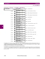
5.6.2 SETTING GROUP
PATH: SETTINGS
GROUPED ELEMENTS
SETTING GROUP 1(6)
Each of the six setting group menus is identical. Setting group 1 (the default active group) automatically becomes active if
no other group is active (see the
Control elements
section for additional details).
If the device incorrectly switches to group 1 after power cycling, upgrade the firmware to version 7.25, 7.31, or later to cor-
rect this issue.
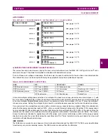
SETTING GROUP 1
LOAD ENCROACHMENT
MESSAGE
PHASE CURRENT
MESSAGE
NEUTRAL CURRENT
MESSAGE
WATTMETRIC
GROUND FAULT
MESSAGE
GROUND CURRENT
MESSAGE
NEGATIVE SEQUENCE
CURRENT
MESSAGE
BREAKER FAILURE
MESSAGE
VOLTAGE ELEMENTS
MESSAGE
POWER
Summary of Contents for F60
Page 10: ...x F60 Feeder Protection System GE Multilin TABLE OF CONTENTS ...
Page 30: ...1 20 F60 Feeder Protection System GE Multilin 1 5 USING THE RELAY 1 GETTING STARTED 1 ...
Page 138: ...4 28 F60 Feeder Protection System GE Multilin 4 2 FACEPLATE INTERFACE 4 HUMAN INTERFACES 4 ...
Page 454: ...5 316 F60 Feeder Protection System GE Multilin 5 10 TESTING 5 SETTINGS 5 ...
Page 500: ...7 14 F60 Feeder Protection System GE Multilin 7 1 COMMANDS 7 COMMANDS AND TARGETS 7 ...
Page 508: ...8 8 F60 Feeder Protection System GE Multilin 8 2 FAULT LOCATOR 8 THEORY OF OPERATION 8 ...
Page 522: ...10 12 F60 Feeder Protection System GE Multilin 10 6 DISPOSAL 10 MAINTENANCE 10 ...
Page 660: ...B 116 F60 Feeder Protection System GE Multilin B 4 MEMORY MAPPING APPENDIX B B ...
Page 706: ...E 10 F60 Feeder Protection System GE Multilin E 1 IEC 60870 5 104 APPENDIX E E ...
Page 718: ...F 12 F60 Feeder Protection System GE Multilin F 2 DNP POINT LISTS APPENDIX F F ...
Page 728: ...H 8 F60 Feeder Protection System GE Multilin H 2 ABBREVIATIONS APPENDIX H H Z Impedance Zone ...
Page 730: ...H 10 F60 Feeder Protection System GE Multilin H 3 WARRANTY APPENDIX H H ...


