


GE Multilin
F60 Feeder Protection System
4-25
4 HUMAN INTERFACES
4.2 FACEPLATE INTERFACE
4
4.2.8 CHANGING SETTINGS
a) ENTERING NUMERICAL DATA
Each numerical setting has its own minimum, maximum, and increment value associated with it. These parameters define
what values are acceptable for a setting.
Two methods of editing and storing a numerical setting value are available.
•
0 to 9 and decimal point
: The relay numeric keypad works the same as that of any electronic calculator. A number is
entered one digit at a time. The leftmost digit is entered first and the rightmost digit is entered last. Pressing the MES-
SAGE LEFT key or pressing the ESCAPE key, returns the original value to the display.
•
VALUE keys
: The VALUE UP key increments the displayed value by the step value, up to the maximum value allowed.
While at the maximum value, pressing the VALUE UP key again allows the setting selection to continue upward from
the minimum value. The VALUE DOWN key decrements the displayed value by the step value, down to the minimum
value. While at the minimum value, pressing the VALUE DOWN key again allows the setting selection to continue
downward from the maximum value.
b) ENTERING ENUMERATION DATA
Enumeration settings have data values which are part of a set, whose members are explicitly defined by a name. A set is
comprised of two or more members.
Enumeration type values are changed using the VALUE keys. The VALUE UP key displays the next selection while the
VALUE DOWN key displays the previous selection.
c) ENTERING ALPHANUMERIC TEXT
Text settings have data values which are fixed in length, but user-defined in character. They can be upper case letters,
lower case letters, numerals, and a selection of special characters.
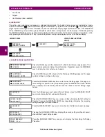
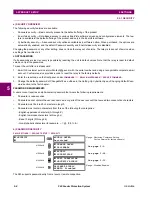
FLASH MESSAGE
TIME: 1.0
s
For example, select the
SETTINGS
PRODUCT SETUP
DISPLAY PROPERTIES
FLASH
MESSAGE TIME
setting.
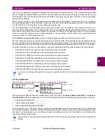
MINIMUM: 0.5
MAXIMUM: 10.0
Press the HELP key to view the minimum and maximum values. Press the HELP key
again to view the next context sensitive help message.
FLASH MESSAGE
TIME: 2.5
s
As an example, set the flash message time setting to 2.5 seconds. Press the appropriate
numeric keys in the sequence “2 . 5". The display message changes as the digits are
being entered.
NEW SETTING
HAS BEEN STORED
Until ENTER is pressed, editing changes are not registered by the relay. Therefore, press
ENTER to store the new value in memory. This flash message momentarily appears as
confirmation of the storing process. Numerical values which contain decimal places are
rounded-off if more decimal place digits are entered than specified by the step value.
ACCESS LEVEL:
Restricted
For example, the selections available for
ACCESS LEVEL
are "Restricted", "Command",
"Setting", and "Factory Service".
ACCESS LEVEL:
Setting
If the
ACCESS LEVEL
needs to be "Setting", press the VALUE keys until the proper selec-
tion is displayed. Press HELP at any time for the context sensitive help messages.
NEW SETTING
HAS BEEN STORED
Changes are not registered by the relay until the ENTER key is pressed. Pressing
ENTER stores the new value in memory. This flash message momentarily appears as
confirmation of the storing process.
Summary of Contents for F60
Page 10: ...x F60 Feeder Protection System GE Multilin TABLE OF CONTENTS ...
Page 30: ...1 20 F60 Feeder Protection System GE Multilin 1 5 USING THE RELAY 1 GETTING STARTED 1 ...
Page 138: ...4 28 F60 Feeder Protection System GE Multilin 4 2 FACEPLATE INTERFACE 4 HUMAN INTERFACES 4 ...
Page 454: ...5 316 F60 Feeder Protection System GE Multilin 5 10 TESTING 5 SETTINGS 5 ...
Page 500: ...7 14 F60 Feeder Protection System GE Multilin 7 1 COMMANDS 7 COMMANDS AND TARGETS 7 ...
Page 508: ...8 8 F60 Feeder Protection System GE Multilin 8 2 FAULT LOCATOR 8 THEORY OF OPERATION 8 ...
Page 522: ...10 12 F60 Feeder Protection System GE Multilin 10 6 DISPOSAL 10 MAINTENANCE 10 ...
Page 660: ...B 116 F60 Feeder Protection System GE Multilin B 4 MEMORY MAPPING APPENDIX B B ...
Page 706: ...E 10 F60 Feeder Protection System GE Multilin E 1 IEC 60870 5 104 APPENDIX E E ...
Page 718: ...F 12 F60 Feeder Protection System GE Multilin F 2 DNP POINT LISTS APPENDIX F F ...
Page 728: ...H 8 F60 Feeder Protection System GE Multilin H 2 ABBREVIATIONS APPENDIX H H Z Impedance Zone ...
Page 730: ...H 10 F60 Feeder Protection System GE Multilin H 3 WARRANTY APPENDIX H H ...


