


GE Multilin
L30 Line Current Differential System
5-147
5 SETTINGS
5.6 GROUPED ELEMENTS
5
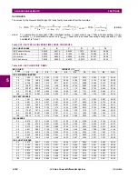
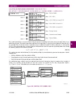
IEC CURVES
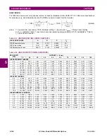
For European applications, the relay offers three standard curves defined in IEC 255-4 and British standard BS142. These
are defined as IEC Curve A, IEC Curve B, and IEC Curve C. The formulae for these curves are:
,
(EQ 5.11)
where:
T
= operate time (in seconds),
TDM
= Multiplier setting,
I
= input current,
I
pickup
= Pickup Current setting,
K
,
E
=
constants,
t
r
= characteristic constant, and
T
RESET
= reset time in seconds (assuming energy capacity is 100%
and
RESET
is “Timed”)
Table 5–17: IEC (BS) INVERSE TIME CURVE CONSTANTS
IEC (BS) CURVE SHAPE
K
E
T
R
IEC Curve A (BS142)
0.140
0.020
9.7
IEC Curve B (BS142)
13.500
1.000
43.2
IEC Curve C (BS142)
80.000
2.000
58.2
IEC Short Inverse
0.050
0.040
0.500
Table 5–18: IEC CURVE TRIP TIMES (IN SECONDS)
MULTIPLIER
(TDM)
CURRENT (
I
/
I
pickup
)
1.5
2.0
3.0
4.0
5.0
6.0
7.0
8.0
9.0
10.0
IEC CURVE A
0.05
0.860
0.501
0.315
0.249
0.214
0.192
0.176
0.165
0.156
0.149
0.10
1.719
1.003
0.630
0.498
0.428
0.384
0.353
0.330
0.312
0.297
0.20
3.439
2.006
1.260
0.996
0.856
0.767
0.706
0.659
0.623
0.594
0.40
6.878
4.012
2.521
1.992
1.712
1.535
1.411
1.319
1.247
1.188
0.60
10.317
6.017
3.781
2.988
2.568
2.302
2.117
1.978
1.870
1.782
0.80
13.755
8.023
5.042
3.984
3.424
3.070
2.822
2.637
2.493
2.376
1.00
17.194
10.029
6.302
4.980
4.280
3.837
3.528
3.297
3.116
2.971
IEC CURVE B
0.05
1.350
0.675
0.338
0.225
0.169
0.135
0.113
0.096
0.084
0.075
0.10
2.700
1.350
0.675
0.450
0.338
0.270
0.225
0.193
0.169
0.150
0.20
5.400
2.700
1.350
0.900
0.675
0.540
0.450
0.386
0.338
0.300
0.40
10.800
5.400
2.700
1.800
1.350
1.080
0.900
0.771
0.675
0.600
0.60
16.200
8.100
4.050
2.700
2.025
1.620
1.350
1.157
1.013
0.900
0.80
21.600
10.800
5.400
3.600
2.700
2.160
1.800
1.543
1.350
1.200
1.00
27.000
13.500
6.750
4.500
3.375
2.700
2.250
1.929
1.688
1.500
IEC CURVE C
0.05
3.200
1.333
0.500
0.267
0.167
0.114
0.083
0.063
0.050
0.040
0.10
6.400
2.667
1.000
0.533
0.333
0.229
0.167
0.127
0.100
0.081
0.20
12.800
5.333
2.000
1.067
0.667
0.457
0.333
0.254
0.200
0.162
0.40
25.600
10.667
4.000
2.133
1.333
0.914
0.667
0.508
0.400
0.323
0.60
38.400
16.000
6.000
3.200
2.000
1.371
1.000
0.762
0.600
0.485
0.80
51.200
21.333
8.000
4.267
2.667
1.829
1.333
1.016
0.800
0.646
1.00
64.000
26.667
10.000
5.333
3.333
2.286
1.667
1.270
1.000
0.808
IEC SHORT TIME
0.05
0.153
0.089
0.056
0.044
0.038
0.034
0.031
0.029
0.027
0.026
0.10
0.306
0.178
0.111
0.088
0.075
0.067
0.062
0.058
0.054
0.052
0.20
0.612
0.356
0.223
0.175
0.150
0.135
0.124
0.115
0.109
0.104
0.40
1.223
0.711
0.445
0.351
0.301
0.269
0.247
0.231
0.218
0.207
0.60
1.835
1.067
0.668
0.526
0.451
0.404
0.371
0.346
0.327
0.311
0.80
2.446
1.423
0.890
0.702
0.602
0.538
0.494
0.461
0.435
0.415
1.00
3.058
1.778
1.113
0.877
0.752
0.673
0.618
0.576
0.544
0.518
T
TDM
K
I I
pickup
E
1
–
---------------------------------------
=
T
RESET
TDM
t
r
1
I I
pickup
2
–
---------------------------------------
=
Summary of Contents for L30
Page 10: ...x L30 Line Current Differential System GE Multilin TABLE OF CONTENTS ...
Page 30: ...1 20 L30 Line Current Differential System GE Multilin 1 5 USING THE RELAY 1 GETTING STARTED 1 ...
Page 370: ...5 244 L30 Line Current Differential System GE Multilin 5 10 TESTING 5 SETTINGS 5 ...
Page 464: ...A 10 L30 Line Current Differential System GE Multilin A 1 PARAMETER LISTS APPENDIX A A ...
Page 600: ...C 30 L30 Line Current Differential System GE Multilin C 7 LOGICAL NODES APPENDIX C C ...
Page 610: ...D 10 L30 Line Current Differential System GE Multilin D 1 IEC 60870 5 104 APPENDIX D D ...
Page 622: ...E 12 L30 Line Current Differential System GE Multilin E 2 DNP POINT LISTS APPENDIX E E ...
Page 634: ...F 12 L30 Line Current Differential System GE Multilin F 3 WARRANTY APPENDIX F F ...
Page 644: ...x L30 Line Current Differential System GE Multilin INDEX ...