


GE Multilin
L30 Line Current Differential System
5-81
5 SETTINGS
5.4 SYSTEM SETUP
5
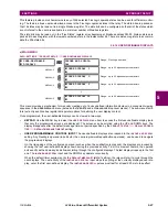
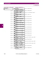
b) IN-ZONE TRANSFORMER
PATH: SETTINGS
SYSTEM SETUP
87L POWER SYSTEM
IN-ZONE TRANSFORMER
The in-zone transformer settings described below ensure that the 87L element will correctly apply magnitude and phase
compensation for the in-zone transformer. To accommodate for the difference in CT ratios at line terminals, the
SETTINGS
GROUPED ELEMENTS
SETTING GROUP 1(6)
LINE DIFFERENTIAL ELEMENTS
CURRENT DIFFERENTIAL
CURRENT
DIFF CT TAP
setting should be used. It is important to properly program the in-zone transformer setting for all terminals to
ensure correct 87L performance.
•
IN-ZONE TRANSFORMER CONNECTION
: This setting is used to indicate the presence and group connection of the
in-zone transformer. The winding angle selection specifies the phase shift of the remote terminal side winding with
respect to the local terminal side winding. For example, for the Dy1 group (delta winding connected to local terminal
side, and wye winding connected to remote terminal side), select the “300° lag” value for the local terminal side. If
there is no in-zone transformer connected, then program this setting as “None” (note that the “0° lag” value does not
correspond to “None”) if there is no in-zone transformer connected. Only one in-zone transformer is allowed for both
two-terminal and three-terminal applications. Enabling in-zone transformer functionality forces the L30 to automatically
remove the zero-sequence component from all terminals currents. It also disables ground differential 87LG functional-
ity and zero-sequence current removal functionality defined by the
ZERO SEQ CURRENT REMOVAL
setting.
•
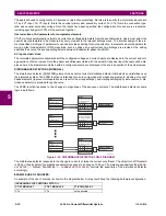
TRANSFORMER LOCATION
: This setting selects the transformer location and is applicable only if the
TRANSFORMER
CONNECTION
setting is not programmed as “None”.
–
Select the “LOCAL-TAP” value if the transformer is present between the local terminal and the tap point or for two-
terminal applications.
–
Select the “REM1-TAP” if the transformer is present between remote terminal 1 and the tap point.
–
Select the “REM2-TAP” if the transformer is present between remote terminal 2 and the tap point.
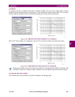
Figure 5–20: ILLUSTRATION OF IN-ZONE TRANSFORMER FOR TWO-TERMINAL AND THREE-TERMINAL LINES
IN-ZONE
TRANSFORMER
IN-ZONE TRANSFORMER
CONNECTION: None
Range: None, 0 to 330° lag in steps of 30°
MESSAGE
TRANSFORMER LOCATION:
LOCAL-TAP
Range: LOCAL-TAP, REM1-TAP, REM2-TAP
$&'5
Summary of Contents for L30
Page 10: ...x L30 Line Current Differential System GE Multilin TABLE OF CONTENTS ...
Page 30: ...1 20 L30 Line Current Differential System GE Multilin 1 5 USING THE RELAY 1 GETTING STARTED 1 ...
Page 370: ...5 244 L30 Line Current Differential System GE Multilin 5 10 TESTING 5 SETTINGS 5 ...
Page 464: ...A 10 L30 Line Current Differential System GE Multilin A 1 PARAMETER LISTS APPENDIX A A ...
Page 600: ...C 30 L30 Line Current Differential System GE Multilin C 7 LOGICAL NODES APPENDIX C C ...
Page 610: ...D 10 L30 Line Current Differential System GE Multilin D 1 IEC 60870 5 104 APPENDIX D D ...
Page 622: ...E 12 L30 Line Current Differential System GE Multilin E 2 DNP POINT LISTS APPENDIX E E ...
Page 634: ...F 12 L30 Line Current Differential System GE Multilin F 3 WARRANTY APPENDIX F F ...
Page 644: ...x L30 Line Current Differential System GE Multilin INDEX ...