


5-44
L30 Line Current Differential System
GE Multilin
5.2 PRODUCT SETUP
5 SETTINGS
5
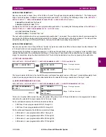
5.2.6 MODBUS USER MAP
PATH: SETTINGS
PRODUCT SETUP
MODBUS USER MAP
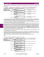
The Modbus user map provides read-only access for up to 256 registers. To obtain a memory map value, enter the desired
address in the
ADDRESS
line (converted from hex to decimal format). The corresponding value displays in the
VALUE
line. A
value of “0” in subsequent register
ADDRESS
lines automatically returns values for the previous
ADDRESS
lines incremented
by “1”. An address value of “0” in the initial register means “none” and values of “0” display for all registers. Different
ADDRESS
values can be entered as required in any of the register positions.
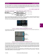
5.2.7 REAL TIME CLOCK
a) MAIN MENU
PATH: SETTINGS
PRODUCT SETUP
REAL TIME CLOCK
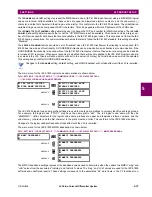
The relay contains a real time clock (RTC) to create timestamps for communications protocols as well as for historical data,
such as event records and oscillography. When the relay restarts, the RTC initializes from an onboard battery-backed
clock, which has the same accuracy as an electronic watch, approximately ±1 minute per month (~23 ppm). Once the RTC
is synchronized with the Precision Time Protocol (PTP), IRIG-B, or SNTP, its accuracy approaches that of the synchroniz-
ing time delivered to the relay. When the L30/L90 channel asymmetry function is used, the relay’s real time clock must be
synchronized to an external time source using PTP or IRIG-B, typically from a global positioning system (GPS) receiver.
The SYNCHRONIZING SOURCE setting configures the priority sequence that the relay uses to determine which of the
available external time sources synchronizes the RTC and the synchrophasor clock. A setting of None causes the RTC and
the synchrophasor clock to free-run. A setting of PP/IRIGB/PTP/SNTP, IRIGB/PP/PTP/SNTP, or PP/PTP/IRIGB/SNTP
causes the relay to track the first source named that is enabled and operational, or free-run if none of these are available.
Here, PP means a time source that is strictly compliant with PP, PTP means a time source that is not strictly compliant with
PP. When a time source fails or recovers, the relay automatically transfers synchronization as required by this setting.
See the
COMMANDS
SET DATE AND TIME
menu item section of this manual to manually set the RTC.
MODBUS USER MAP
ADDRESS
1:
0
VALUE:
0
Range: 0 to 65535 in steps of 1
MESSAGE
ADDRESS
2:
0
VALUE:
0
Range: 0 to 65535 in steps of 1
MESSAGE
ADDRESS
3:
0
VALUE:
0
Range: 0 to 65535 in steps of 1
MESSAGE
ADDRESS 256:
0
VALUE:
0
Range: 0 to 65535 in steps of 1
REAL TIME
CLOCK
SYNCRONIZING SOURCE:
None
Range: None, PP/IRIG-B/PTP/SNTP, IRIG-B/PP/PTP/
SNTP, PP/PTP/IRIG-B/SNTP
MESSAGE
REAL TIME CLOCK
EVENTS: Disabled
Range: Disabled, Enabled
MESSAGE
IRIG-B SIGNAL TYPE:
None
Range: None, DC Shift, Amplitude Modulated
PRECISION TIME
PROTOCOL (1588)
See below
EE
MESSAGE
SNTP PROTOCOL
See below
MESSAGE
LOCAL TIME
See below
Summary of Contents for L30
Page 10: ...x L30 Line Current Differential System GE Multilin TABLE OF CONTENTS ...
Page 30: ...1 20 L30 Line Current Differential System GE Multilin 1 5 USING THE RELAY 1 GETTING STARTED 1 ...
Page 370: ...5 244 L30 Line Current Differential System GE Multilin 5 10 TESTING 5 SETTINGS 5 ...
Page 464: ...A 10 L30 Line Current Differential System GE Multilin A 1 PARAMETER LISTS APPENDIX A A ...
Page 600: ...C 30 L30 Line Current Differential System GE Multilin C 7 LOGICAL NODES APPENDIX C C ...
Page 610: ...D 10 L30 Line Current Differential System GE Multilin D 1 IEC 60870 5 104 APPENDIX D D ...
Page 622: ...E 12 L30 Line Current Differential System GE Multilin E 2 DNP POINT LISTS APPENDIX E E ...
Page 634: ...F 12 L30 Line Current Differential System GE Multilin F 3 WARRANTY APPENDIX F F ...
Page 644: ...x L30 Line Current Differential System GE Multilin INDEX ...