


9-8
B90 Low Impedance Bus Differential System
GE Multilin
9.4 SLOPES AND HIGH SET THRESHOLD
9 APPLICATION OF SETTINGS
9
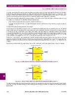
9.4.5 EXTERNAL FAULTS ON C-4
The following table presents the results of analysis of an external fault on circuit C-4 (C-4 is connected to the North bus; C-
3 and C-5 are connected to the South bus).
By comparing the secondary currents (column 3 in the table below) with the limits of linear operation for the CTs (column 4
in the Limits of Linear Operations of the CTs table shown earlier), it is concluded that none of the CTs will saturate due to
the AC currents during this fault.
Columns 6 and 7 of the following table summarize the DC saturation threat for the fault on C-4. CT-4, CT-6, CT-7, and CT-
8 may saturate due to the DC components and may generate a spurious differential signal for both the North and South bus
relays depending on the bus configuration. The saturation will not occur before 5.85 ms and will be detected by the Satura-
tion Detector.
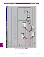
9.4.6 EXTERNAL FAULTS ON C-5
The following table presents the results of analysis of an external fault on circuit C-5 (C-5 is connected to the North bus; C-
3 and C-4 are connected to the South bus).
By comparing the secondary currents (column 3 in the table below) with the limits of linear operation for the CTs (column 4
in the Limits of Linear Operations of the CTs table shown earlier), it is concluded that none of the CTs will saturate due to
the AC currents during this fault.
Columns 6 and 7 of the following table summarize the DC saturation threat for the fault on C-5. CT-4, CT-5, CT-7, and CT-
8 may saturate due to the DC components and may generate a spurious differential signal for both the North and South bus
relays depending on the bus configuration. The saturation will not occur before 4.83 ms and will be detected by the Satura-
tion Detector.
Table 9–7: EXTERNAL FAULT CALCULATIONS ON C-4
CT
I
FAULT
(KA)
I
FAULT
(A SEC)
T
DC
(MS)
AC
SATURATION
DC
SATURATION
T
SAT
(MS)
CT-1
0
0.00
N/A
No
No
N/A
CT-2
0
0.00
N/A
No
No
N/A
CT-3
6.0
25.00
5
No
No
N/A
CT-4
9.0
45.00
40
No
Yes
5.85
CT-6
3.0
15.00
40
No
Yes
35.25
CT-7, CT-8
9.0
37.50
40
No
Yes
9.40
Table 9–8: EXTERNAL FAULT CALCULATIONS ON C-5
CT
I
FAULT
(KA)
I
FAULT
(A SEC)
T
DC
(MS)
AC
SATURATION
DC
SATURATION
T
SAT
(MS)
CT-1
0
0.00
N/A
No
No
N/A
CT-2
0
0.00
N/A
No
No
N/A
CT-3
6.0
25.00
5
No
No
N/A
CT-4
5.0
25.00
30
No
Yes
15.19
CT-5
11.0
55.00
30
No
Yes
4.83
CT-7, CT-8
11.0
45.83
30
No
Yes
7.16
Summary of Contents for B90
Page 10: ...x B90 Low Impedance Bus Differential System GE Multilin TABLE OF CONTENTS ...
Page 284: ...5 166 B90 Low Impedance Bus Differential System GE Multilin 5 8 TESTING 5 SETTINGS 5 ...
Page 334: ...10 8 B90 Low Impedance Bus Differential System GE Multilin 10 2 BATTERIES 10 MAINTENANCE 10 ...
Page 338: ...A 4 B90 Low Impedance Bus Differential System GE Multilin A 1 PARAMETER LISTS APPENDIX A A ...
Page 460: ...C 30 B90 Low Impedance Bus Differential System GE Multilin C 7 LOGICAL NODES APPENDIX C C ...
Page 476: ...E 10 B90 Low Impedance Bus Differential System GE Multilin E 1 IEC 60870 5 104 APPENDIX E E ...
Page 502: ...viii B90 Low Impedance Bus Differential System GE Multilin INDEX ...