


9-6
B90 Low Impedance Bus Differential System
GE Multilin
9.4 SLOPES AND HIGH SET THRESHOLD
9 APPLICATION OF SETTINGS
9
9.4SLOPES AND HIGH SET THRESHOLD
9.4.1 DESCRIPTION
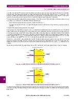
To set the higher slope and threshold of the high set (unbiased) differential operation, external faults must be analyzed.
Consider an external fault for the North bus relay. It is justified to assume bus configurations that give maximum stress to
the maximum number of CTs. For this purpose we will assume the tie breaker, B-7 closed; all the circuitry capable of sup-
plying the fault current to be in service; moreover, they are connected to the South bus in order to analyze the CT-7 and CT-
8 carrying the fault current.
9.4.2 EXTERNAL FAULTS ON C-1
The table below presents the results of analysis of an external fault on circuit C-1 (C-1 is connected to the North bus; C-3,
C-4, and C-5 are connected to the South bus).
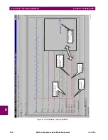
For security reasons, it has been assumed that the fault current being a sum of several contributors (C-3, C-4, and C-5 in
this case) has a time constant of the DC component of the maximum among the time constants of the contributors. The
fault current is supplied from circuits C-3, C-4, and C-5 connected to the South bus, thus through CT-3, CT-4, and CT-6.
The current passes through the tie breaker threatening saturation of CT-7 and CT-8.
By comparing the secondary currents (column 3 in the table below) with the limits of linear operation for the CTs (column 4
in the Limits of Linear Operations of the CTs table earlier), it is concluded that CT-1 will saturate during this fault, producing
a spurious differential signal for the North bus zone differential protection. All other CTs will not saturate due to the AC com-
ponents. The amount of the spurious differential current (magnetizing current of CT-1) can be calculated using the burden,
magnetizing characteristic and primary current of the noted CT by solving the following equations:
(EQ 9.4)
For
I
s
= 116.67 A,
R
s
= 1.61
and the characteristic shown earlier in the Approximate CT Magnetizing Characteristics fig-
ure, the solution is
I
magnetizing
= 29.73 A,
I
relay
= 112.8 A.
The magnetizing current of the saturated CT-1 will appear to the differential element protecting the North bus as a differen-
tial signal of 29.73 A, while the restraint signal will be the maximum of the bus currents (112.8 A in this case). Conse-
quently, the higher slope of the characteristic should not be lower than 29.73 A / 112.8 A, or 26%, and the pick up of the
high set differential elements should not be lower than 29.73 A, or 2.97 pu.
The CTs identified as operating in the linear mode as far as the AC components are considered may, however, saturate due
to the DC components. Saturation will not occur if
, where
is radian system frequency (2
f).
If the above condition is violated, saturation will occur but not before:
(EQ 9.5)
Columns 6 and 7 of the table below summarize the DC saturation threat for the fault on C-1. CT-4, CT-6, CT-7, and CT-8
may saturate due to the DC components and may generate spurious differential signal for both the North and South bus
relays depending on the bus configuration. The saturation will not occur before 4.7 ms and will be detected by the Satura-
tion Detector.
The transient saturation of the CTs due to the DC component may be neglected when setting the slopes of the characteris-
tic as the saturation will be detected and the relay will use the current directional principle. It must however, be taken into
account when setting the high set (unbiased) differential element.
Table 9–4: EXTERNAL FAULT CALCULATIONS ON C-1
CT
I
FAULT
(KA)
I
FAULT
(A SEC)
T
DC
(MS)
AC
SATURATION
DC
SATURATION
T
SAT
(MS)
CT-1
14.0
116.67
40
Yes
Yes
N/A
CT-2
0
0.00
N/A
No
No
N/A
CT-3
6.0
25.00
5
No
No
N/A
CT-4
5.0
25.00
30
No
Yes
15.19
CT-6
3.0
15.00
40
No
Yes
35.25
CT-7, CT-8
14.0
58.33
40
No
Yes
4.70
I
relay
I
s
2
I
magnetizing
2
–
=
I
relay
R
s
V
magnetizing
=
V
sat
I
s
R
s
1
T
dc
+
T
sat
T
dc
–
1
V
sat
I
s
R
s
1
–
T
dc
----------------------------------------
–
ln
=
Summary of Contents for B90
Page 10: ...x B90 Low Impedance Bus Differential System GE Multilin TABLE OF CONTENTS ...
Page 284: ...5 166 B90 Low Impedance Bus Differential System GE Multilin 5 8 TESTING 5 SETTINGS 5 ...
Page 334: ...10 8 B90 Low Impedance Bus Differential System GE Multilin 10 2 BATTERIES 10 MAINTENANCE 10 ...
Page 338: ...A 4 B90 Low Impedance Bus Differential System GE Multilin A 1 PARAMETER LISTS APPENDIX A A ...
Page 460: ...C 30 B90 Low Impedance Bus Differential System GE Multilin C 7 LOGICAL NODES APPENDIX C C ...
Page 476: ...E 10 B90 Low Impedance Bus Differential System GE Multilin E 1 IEC 60870 5 104 APPENDIX E E ...
Page 502: ...viii B90 Low Impedance Bus Differential System GE Multilin INDEX ...