


GE Multilin
B90 Low Impedance Bus Differential System
9-1
9 APPLICATION OF SETTINGS
9.1 OVERVIEW
9
9 APPLICATION OF SETTINGS 9.1OVERVIEW
9.1.1 INTRODUCTION
This chapter provides an example of setting calculations for a sample bus. The selected example includes various bus con-
figurations to clarify a number of typical situations. Both the bus configuration and numerical data used are not meant to
reflect any specific
utility practice or design standards.
It is also assumed that the CTs have been selected without considering a B90 application, but the B90 settings are to be
calculated for proper relay application. The CT data used in this example are kept to a minimum and in a generic form. The
CT data does not reflect any particular notation or national standards.
The analysis provided in this chapter has been performed with the following goals:
•
The limits of linear operation of the CTs considering zero remanent flux have been determined in order to select the
high breakpoint settings of the biased differential characteristic.
•
The limits of linear operation of the CTs considering a remanent flux of 80% have been determined in order to select
the low breakpoint settings of the biased differential characteristic.
•
Saturation of the CTs has been analyzed in order to select the higher slope of the biased differential characteristic and
the high set differential overcurrent setting.
The analysis tools and safety margins applied are examples only and do not reflect any particular protection philosophy.
Typically, for the CT saturation related calculations, it is sufficient to consider the weakest (most prone to saturation) CT
connected to the bus and the total bus fault current combined with the longest time constant among all the circuits con-
nected to the bus. This chapter provides more detailed analysis (see the
Slopes and High Set Threshold
section) in order to
illustrate the idea of using setting groups to enhance the B90 performance when the bus configuration changes (see the
Enhancing Relay Performance
section).
9.1.2 SAMPLE BUSBAR AND DATA
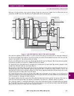
The following figure shows a double bus arrangement with North and South buses. This station has five circuits (C-1
through C-5) and a tiebreaker (B-7). Circuit C-1 is connected to the North bus; circuits C-2, C-3 and C-4 can be routed to
either bus via switches S-1 through S-6; circuit C-5 can be connected to either bus via breakers B-5 and B-6.
Figure 9–1: SAMPLE BUS CONFIGURATION
836731A2.CDR
NORTH BUS
SOUTH BUS
CT-8
B-5
B-6
CT-5
CT-6
S-5
S-6
B-4
CT-4
S-3
S-4
B-3
CT-3
S-1
S-2
B-2
CT-2
CT-1
B-1
C-1
C-2
C-4
C-3
C-5
CT-7
B-7
Summary of Contents for B90
Page 10: ...x B90 Low Impedance Bus Differential System GE Multilin TABLE OF CONTENTS ...
Page 284: ...5 166 B90 Low Impedance Bus Differential System GE Multilin 5 8 TESTING 5 SETTINGS 5 ...
Page 334: ...10 8 B90 Low Impedance Bus Differential System GE Multilin 10 2 BATTERIES 10 MAINTENANCE 10 ...
Page 338: ...A 4 B90 Low Impedance Bus Differential System GE Multilin A 1 PARAMETER LISTS APPENDIX A A ...
Page 460: ...C 30 B90 Low Impedance Bus Differential System GE Multilin C 7 LOGICAL NODES APPENDIX C C ...
Page 476: ...E 10 B90 Low Impedance Bus Differential System GE Multilin E 1 IEC 60870 5 104 APPENDIX E E ...
Page 502: ...viii B90 Low Impedance Bus Differential System GE Multilin INDEX ...