


GE Multilin
B90 Low Impedance Bus Differential System
8-7
8 THEORY OF OPERATION
8.5 SATURATION DETECTOR
8
8.5SATURATION DETECTOR
8.5.1 CT SATURATION DETECTION
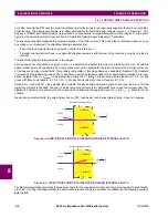
The saturation detector of the B90 takes advantage of the fact that any CT operates correctly for a short period of time even
under very large primary currents that would subsequently cause a very deep saturation. As a result of that, in the case of
an external fault, the differential current stays very low during the initial period of linear operation of the CTs while the
restraining signal develops rapidly. Once one or more CTs saturate, the differential current will increase. The restraining sig-
nal, however, yields by at least a few milliseconds. During internal faults, both the differential and restraining currents
develop simultaneously. This creates characteristic patterns for the differential - restraining trajectory as depicted below.
Figure 8–6: CT SATURATION DETECTION: INTERNAL & EXTERNAL FAULT PATTERNS
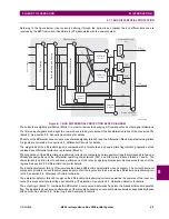
The CT saturation condition is declared by the saturation detector when the magnitude of the restraining signal becomes
larger than the higher breakpoint (HIGH BPNT) and at the same time the differential current is below the first slope (LOW
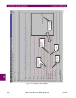
SLOPE). The said condition is of a transient nature and requires a seal-in. A special logic in the form of a “state machine” is
used for this purpose as depicted in the following figure on saturation detector state machine.
As the phasor estimator introduces a delay into the measurement process, the aforementioned saturation test would fail to
detect CT saturation occurring very fast. In order to cope with very fast CT saturation, another condition is checked that
uses relations between the signals at the waveform level. The basic principle is similar to that described above. Addition-
ally, the sample-based stage of the saturation detector uses the time derivative of the restraining signal (di/dt) to better
trace the saturation pattern shown in the above diagram.
The saturation detector is capable of detecting saturation occurring in approximately 2 ms into a fault. It is worth emphasiz-
ing that the saturation detector, although having no dedicated settings, uses the main differential characteristic for proper
operation. This must be kept in mind when setting the characteristic as its parameters must retain their original meaning.
The operation of the saturation detector is available as the FlexLogic operand BUS 1(4) SAT.
Figure 8–7: SATURATION DETECTOR STATE MACHINE
836728A1.CDR
di
ffer
enti
al
restraining
OPERATE
BLOCK
IN
TER
N
A
L
F
AU
L
T
P
A
TTER
N
EX
TER
N
A
L
F
A
U
L
T
PAT
TER
N
EXTERNAL FAULT
PATTERN
NORMAL
SAT := 0
EXTERNAL
FAULT
SAT := 1
EXTERNAL
FAULT and CT
SATURATION
SAT := 1
The differential
characteristic
entered
The differential-
restraining trajectory
out of the differential
characteristic for a
certain period of time
saturation
condition
The differential
current below the
first slope for a
certain period of
time
836729A1.CDR
Summary of Contents for B90
Page 10: ...x B90 Low Impedance Bus Differential System GE Multilin TABLE OF CONTENTS ...
Page 284: ...5 166 B90 Low Impedance Bus Differential System GE Multilin 5 8 TESTING 5 SETTINGS 5 ...
Page 334: ...10 8 B90 Low Impedance Bus Differential System GE Multilin 10 2 BATTERIES 10 MAINTENANCE 10 ...
Page 338: ...A 4 B90 Low Impedance Bus Differential System GE Multilin A 1 PARAMETER LISTS APPENDIX A A ...
Page 460: ...C 30 B90 Low Impedance Bus Differential System GE Multilin C 7 LOGICAL NODES APPENDIX C C ...
Page 476: ...E 10 B90 Low Impedance Bus Differential System GE Multilin E 1 IEC 60870 5 104 APPENDIX E E ...
Page 502: ...viii B90 Low Impedance Bus Differential System GE Multilin INDEX ...