


6-8
B90 Low Impedance Bus Differential System
GE Multilin
6.3 METERING
6 ACTUAL VALUES
6
6.3METERING
6.3.1 PARALLEL REDUNDANCY PROTOCOL (PRP)
The Parallel Redundancy Protocol (PRP) defines a redundancy protocol for high availability in substation automation net-
works.
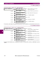
PATH: ACTUAL VALUES
STATUS
PRP
The B90 Low Impedance Bus Differential System is provided with optional PRP capability. This feature is
specified as a software option at the time of ordering. See the
Order Codes
section in chapter 2 for details.
TOTAL RECEIVED PORT A
is a counter for total messages received (either from DANPs or from SANs) on Port A.
TOTAL RECEIVED PORT B
is a counter for total messages received (either from DANPs or from SANs) on Port B.
TOTAL ERRORS
is a counter for total messages received with an error (bad port code, frame length too short).
MISMATCHES PORT A
is a counter for total messages received with an error on Port A (PRP frame, but port received through
and LAN ID in the frame do not match).
MISMATCHES PORT B
is a counter for total messages received with an error on Port B (PRP frame, but port received through
and LAN ID in the frame do not match).
6.3.2 METERING CONVENTIONS
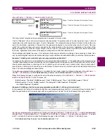
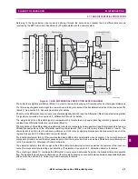
a) UR CONVENTION FOR MEASURING PHASE ANGLES
All phasors calculated by UR-series relays and used for protection, control and metering functions are rotating phasors that
maintain the correct phase angle relationships with each other at all times.
For display and oscillography purposes, all phasor angles in a given relay are referred to an AC input channel pre-selected
by the
SETTINGS
SYSTEM SETUP
POWER SYSTEM
FREQUENCY AND PHASE REFERENCE
setting. This setting
defines a particular AC signal source to be used as the reference.
If the AC signal pre-selected by the relay upon configuration is not measurable, the phase angles are not referenced. The
phase angles are assigned as positive in the leading direction, and are presented as negative in the lagging direction, to
more closely align with power system metering conventions. This is illustrated below.
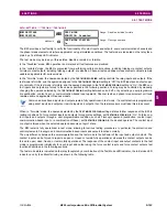
PRP
Total Rx Port A:
Range: 0 to 4G, blank if PRP disabled
MESSAGE
Total Rx Port B:
Range: 0 to 4G, blank if PRP disabled
MESSAGE
Total Errors:
Range: 0 to 4G, blank if PRP disabled
MESSAGE
Mismatches Port A:
Range: 0 to 4G, blank if PRP disabled
MESSAGE
Mismatches Port B:
Range: 0 to 4G, blank if PRP disabled
Summary of Contents for B90
Page 10: ...x B90 Low Impedance Bus Differential System GE Multilin TABLE OF CONTENTS ...
Page 284: ...5 166 B90 Low Impedance Bus Differential System GE Multilin 5 8 TESTING 5 SETTINGS 5 ...
Page 334: ...10 8 B90 Low Impedance Bus Differential System GE Multilin 10 2 BATTERIES 10 MAINTENANCE 10 ...
Page 338: ...A 4 B90 Low Impedance Bus Differential System GE Multilin A 1 PARAMETER LISTS APPENDIX A A ...
Page 460: ...C 30 B90 Low Impedance Bus Differential System GE Multilin C 7 LOGICAL NODES APPENDIX C C ...
Page 476: ...E 10 B90 Low Impedance Bus Differential System GE Multilin E 1 IEC 60870 5 104 APPENDIX E E ...
Page 502: ...viii B90 Low Impedance Bus Differential System GE Multilin INDEX ...