


GE Multilin
B90 Low Impedance Bus Differential System
5-161
5 SETTINGS
5.7 INPUTS/OUTPUTS
5
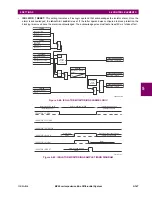
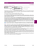
DIRECT OUT 2 OPERAND:
"
HYB POTT TX1
"
DIRECT OUT 3 OPERAND:
"
DIRECT INPUT 5
" (forward a message from 1 to 3)
DIRECT OUT 4 OPERAND:
"
DIRECT INPUT 6
" (forward a message from 3 to 1)
Signal flow between the three IEDs is shown in the figure below:
Figure 5–72: SIGNAL FLOW FOR DIRECT INPUT AND OUTPUT – EXAMPLE 3
In three-terminal applications, both the remote terminals must grant permission to trip. Therefore, at each terminal, direct
inputs 5 and 6 should be ANDed in FlexLogic and the resulting operand configured as the permission to trip (
HYB POTT RX1
setting).
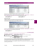
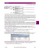
5.7.11 IEC 61850 GOOSE ANALOGS
PATH: SETTINGS
INPUTS/OUTPUTS
IEC 61850 GOOSE ANALOGS
GOOSE ANALOG INPUT 1(32)
The IEC 61850 GOOSE analog inputs feature allows the transmission of analog values between any two UR-series
devices. The following settings are available for each GOOSE analog input.
•
ANALOG 1 DEFAULT
: This setting specifies the value of the GOOSE analog input when the sending device is offline
and the
ANALOG 1 DEFAULT MODE
is set to “Default Value”.This setting is stored as an IEEE 754 / IEC 60559 floating
point number. Because of the large range of this setting, not all possible values can be stored. Some values may be
rounded to the closest possible floating point number.
•
ANALOG 1 DEFAULT MODE
: When the sending device is offline and this setting is “Last Known”, the value of the
GOOSE analog input remains at the last received value. When the sending device is offline and this setting value is
“Default Value”, then the value of the GOOSE analog input is defined by the
ANALOG 1 DEFAULT
setting.
•
GOOSE ANALOG 1 UNITS
: This setting specifies a four-character alphanumeric string that can is used in the actual
values display of the corresponding GOOSE analog input value.
GOOSE Analogs are floating-point values, with no units. The GOOSE UNIT and PU base settings allow the user to
configure GOOSE Analog, so that it can be used in a FlexElement.
GOOSE Analogs that represent current, voltage, power, frequency, angles, or power factor can be used in a FlexEle-
ment. The following text must be used in the UNITS setting, to represent these types of analogs: A, V, W, var, VA, Hz,
deg, and no text (blank setting) for power factor.
GOOSE ANALOG
INPUT 1
ANALOG 1
DEFAULT:
1000.000
Range: –1000000.000 to 1000000.000 in steps of 0.001
MESSAGE
ANALOG 1
DEFAULT
MODE: Default Value
Range: Default Value, Last Known
MESSAGE
GOOSE ANALOG 1
UNITS:
Range: up to 4 alphanumeric characters
MESSAGE
GOOSE ANALOG 1 PU:
1.000
Range: 0.000 to 1000000000.000 in steps of 0.001
842717A1.CDR
UR IED 3
UR IED 2
UR IED 1
DIRECT OUT 2 = HYB POTT TX1
DIRECT INPUT 5
DIRECT INPUT 6
DIRECT OUT 2 = HYB POTT TX1
DIRECT INPUT 5
DIRECT INPUT 6
DIRECT OUT 2 = HYB POTT TX1
DIRECT INPUT 6
DIRECT OUT 4 = DIRECT INPUT 6
DIRECT OUT 3 = DIRECT INPUT 5
DIRECT INPUT 5
Summary of Contents for B90
Page 10: ...x B90 Low Impedance Bus Differential System GE Multilin TABLE OF CONTENTS ...
Page 284: ...5 166 B90 Low Impedance Bus Differential System GE Multilin 5 8 TESTING 5 SETTINGS 5 ...
Page 334: ...10 8 B90 Low Impedance Bus Differential System GE Multilin 10 2 BATTERIES 10 MAINTENANCE 10 ...
Page 338: ...A 4 B90 Low Impedance Bus Differential System GE Multilin A 1 PARAMETER LISTS APPENDIX A A ...
Page 460: ...C 30 B90 Low Impedance Bus Differential System GE Multilin C 7 LOGICAL NODES APPENDIX C C ...
Page 476: ...E 10 B90 Low Impedance Bus Differential System GE Multilin E 1 IEC 60870 5 104 APPENDIX E E ...
Page 502: ...viii B90 Low Impedance Bus Differential System GE Multilin INDEX ...