


GE Multilin
B90 Low Impedance Bus Differential System
5-91
5 SETTINGS
5.3 SYSTEM SETUP
5
5.3.3 FLEXCURVES
a) SETTINGS
PATH: SETTINGS
SYSTEM SETUP
FLEXCURVES
FLEXCURVE A(D)
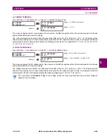
FlexCurves A through D have settings for entering times to reset and operate at the following pickup levels: 0.00 to 0.98
and 1.03 to 20.00. This data is converted into two continuous curves by linear interpolation between data points. To enter a
custom FlexCurve, enter the reset and operate times (using the VALUE keys) for each selected pickup point (using the
MESSAGE UP/DOWN keys) for the desired protection curve (A, B, C, or D).
The relay using a given FlexCurve applies linear approximation for times between the user-entered points. Special
care must be applied when setting the two points that are close to the multiple of pickup of 1; that is, 0.98 pu and
1.03 pu. It is recommended to set the two times to a similar value; otherwise, the linear approximation may result in
undesired behavior for the operating quantity that is close to 1.00 pu.
FLEXCURVE A
FLEXCURVE A TIME AT
0.00 xPKP:
0 ms
Range: 0 to 65535 ms in steps of 1
Table 5–11: FLEXCURVE TABLE
RESET
TIME
MS
RESET
TIME
MS
OPERATE
TIME
MS
OPERATE
TIME
MS
OPERATE
TIME
MS
OPERATE
TIME
MS
0.00
0.68
1.03
2.9
4.9
10.5
0.05
0.70
1.05
3.0
5.0
11.0
0.10
0.72
1.1
3.1
5.1
11.5
0.15
0.74
1.2
3.2
5.2
12.0
0.20
0.76
1.3
3.3
5.3
12.5
0.25
0.78
1.4
3.4
5.4
13.0
0.30
0.80
1.5
3.5
5.5
13.5
0.35
0.82
1.6
3.6
5.6
14.0
0.40
0.84
1.7
3.7
5.7
14.5
0.45
0.86
1.8
3.8
5.8
15.0
0.48
0.88
1.9
3.9
5.9
15.5
0.50
0.90
2.0
4.0
6.0
16.0
0.52
0.91
2.1
4.1
6.5
16.5
0.54
0.92
2.2
4.2
7.0
17.0
0.56
0.93
2.3
4.3
7.5
17.5
0.58
0.94
2.4
4.4
8.0
18.0
0.60
0.95
2.5
4.5
8.5
18.5
0.62
0.96
2.6
4.6
9.0
19.0
0.64
0.97
2.7
4.7
9.5
19.5
0.66
0.98
2.8
4.8
10.0
20.0
NOTE
Summary of Contents for B90
Page 10: ...x B90 Low Impedance Bus Differential System GE Multilin TABLE OF CONTENTS ...
Page 284: ...5 166 B90 Low Impedance Bus Differential System GE Multilin 5 8 TESTING 5 SETTINGS 5 ...
Page 334: ...10 8 B90 Low Impedance Bus Differential System GE Multilin 10 2 BATTERIES 10 MAINTENANCE 10 ...
Page 338: ...A 4 B90 Low Impedance Bus Differential System GE Multilin A 1 PARAMETER LISTS APPENDIX A A ...
Page 460: ...C 30 B90 Low Impedance Bus Differential System GE Multilin C 7 LOGICAL NODES APPENDIX C C ...
Page 476: ...E 10 B90 Low Impedance Bus Differential System GE Multilin E 1 IEC 60870 5 104 APPENDIX E E ...
Page 502: ...viii B90 Low Impedance Bus Differential System GE Multilin INDEX ...