


4-26
B90 Low Impedance Bus Differential System
GE Multilin
4.3 FACEPLATE INTERFACE
4 HUMAN INTERFACES
4
3.
Press the MESSAGE DOWN key until the
INSTALLATION
message appears on the display.
4.
Press the MESSAGE RIGHT key until the
RELAY SETTINGS:
Not Programmed
message is displayed.
5.
After the
RELAY SETTINGS:
Not Programmed
message appears on the display, press the VALUE keys change the
selection to "Programmed".
6.
Press the ENTER key.
7.
When the "NEW SETTING HAS BEEN STORED" message appears, the relay is in "Programmed" state and the In
Service LED turns on.
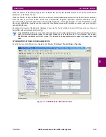
e) ENTERING INITIAL PASSWORDS
The information in this section refers to password security. For information on how to set or change CyberSentry pass-
words, see the Settings > Product Setup > Security > CyberSentry section in the next chapter.
The B90 supports password entry from a local or remote connection.
Local access is defined as any access to settings or commands via the faceplate interface. This includes both keypad entry
and the faceplate RS232 connection. Remote access is defined as any access to settings or commands via any rear com-
munications port. This includes both Ethernet and RS485 connections. Any changes to the local or remote passwords
enables this functionality.
To enter the initial setting (or command) password, proceed as follows:
1.
Press the MENU key until the
SETTINGS
header flashes momentarily and the
PRODUCT SETUP
message appears on the
display.
2.
Press the MESSAGE RIGHT key until the
ACCESS LEVEL
message appears on the display.
3.
Press the MESSAGE DOWN key until the
CHANGE LOCAL PASSWORDS
message appears on the display.
SETTINGS
SETTINGS
PRODUCT SETUP
SECURITY
DISPLAY
PROPERTIES
INSTALLATION
RELAY SETTINGS:
Not Programmed
RELAY SETTINGS:
Not Programmed
RELAY SETTINGS:
Programmed
NEW SETTING
HAS BEEN STORED
Summary of Contents for B90
Page 10: ...x B90 Low Impedance Bus Differential System GE Multilin TABLE OF CONTENTS ...
Page 284: ...5 166 B90 Low Impedance Bus Differential System GE Multilin 5 8 TESTING 5 SETTINGS 5 ...
Page 334: ...10 8 B90 Low Impedance Bus Differential System GE Multilin 10 2 BATTERIES 10 MAINTENANCE 10 ...
Page 338: ...A 4 B90 Low Impedance Bus Differential System GE Multilin A 1 PARAMETER LISTS APPENDIX A A ...
Page 460: ...C 30 B90 Low Impedance Bus Differential System GE Multilin C 7 LOGICAL NODES APPENDIX C C ...
Page 476: ...E 10 B90 Low Impedance Bus Differential System GE Multilin E 1 IEC 60870 5 104 APPENDIX E E ...
Page 502: ...viii B90 Low Impedance Bus Differential System GE Multilin INDEX ...