


4-22
B90 Low Impedance Bus Differential System
GE Multilin
4.3 FACEPLATE INTERFACE
4 HUMAN INTERFACES
4
2.
Pop out the LED module and/or the blank module with a screwdriver as shown below. Be careful not to damage the
plastic covers.
3.
Place the left side of the customized module back to the front panel frame, then snap back the right side.
4.
Put the clear Lexan front cover back into place.
The following items are required to customize the B90 display module:
•
Black and white or color printer (color preferred)
•
Microsoft Word 97 or later software for editing the template
•
1 each of: 8.5" x 11" white paper, exacto knife, ruler, custom display module (GE Multilin Part Number: 1516-0069),
and a custom module cover (GE Multilin Part Number: 1502-0015)
The following procedure describes how to customize the B90 display module:
1.
Open the LED panel customization template with Microsoft Word. Add text in places of the
LED x
text placeholders on
the template(s). Delete unused place holders as required.
2.
When complete, save the Word file to your computer for future use.
3.
Print the template(s) to a local printer.
4.
From the printout, cut-out the Background Template from the three windows, using the cropmarks as a guide.
5.
Put the Background Template on top of the custom display module (GE Multilin Part Number: 1513-0069) and snap the
clear custom module cover (GE Multilin Part Number: 1502-0015) over it and the templates.
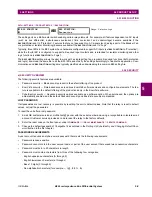
4.3.4 DISPLAY
All messages are displayed on a backlit liquid crystal display (LCD) to make them visible under poor lighting conditions.
While the keypad and display are not actively being used, the display defaults to user-defined messages. Any high-priority
event-driven message automatically overrides the default message and appears on the display.
Settings files conversion from previous firmware versions is supported.
4.3.5 KEYPAD
Display messages are organized into pages under the following headings: actual values, settings, commands, and targets.
The MENU key navigates through these pages. Each heading page is divided further into logical subgroups.
The MESSAGE keys navigate through the subgroups. The VALUE keys increment or decrement numerical setting values
when in programming mode. These keys also scroll through alphanumeric values in the text edit mode. Alternatively, val-
ues can be entered with the numeric keypad.
The decimal key initiates and advances to the next character in text edit mode or enters a decimal point.
The HELP key can be pressed at any time for context-sensitive help messages.
The ENTER key stores altered setting values.
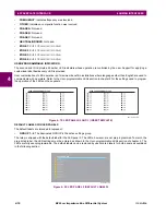
F60
FEEDER MANAGEMENT RELAY
( LED MODULE )
( BLANK MODULE )
R
842722A1.CDR
Summary of Contents for B90
Page 10: ...x B90 Low Impedance Bus Differential System GE Multilin TABLE OF CONTENTS ...
Page 284: ...5 166 B90 Low Impedance Bus Differential System GE Multilin 5 8 TESTING 5 SETTINGS 5 ...
Page 334: ...10 8 B90 Low Impedance Bus Differential System GE Multilin 10 2 BATTERIES 10 MAINTENANCE 10 ...
Page 338: ...A 4 B90 Low Impedance Bus Differential System GE Multilin A 1 PARAMETER LISTS APPENDIX A A ...
Page 460: ...C 30 B90 Low Impedance Bus Differential System GE Multilin C 7 LOGICAL NODES APPENDIX C C ...
Page 476: ...E 10 B90 Low Impedance Bus Differential System GE Multilin E 1 IEC 60870 5 104 APPENDIX E E ...
Page 502: ...viii B90 Low Impedance Bus Differential System GE Multilin INDEX ...