


4-16
B90 Low Impedance Bus Differential System
GE Multilin
4.3 FACEPLATE INTERFACE
4 HUMAN INTERFACES
4
•
FREQUENCY
: Indicates frequency was involved.
•
OTHER
: Indicates a composite function was involved.
•
PHASE A
: Not used.
•
PHASE B
: Not used.
•
PHASE C
: Not used.
•
NEUTRAL/GROUND
: Not used.
•
ZONE 1
:
BUS 1 OP asserted (or active)
.
•
ZONE 2
:
BUS 2 OP asserted (or active)
.
•
ZONE 3
:
BUS 3 OP asserted (or active)
.
•
ZONE 4
:
BUS 4 OP asserted (or active)
.
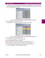
USER-PROGRAMMABLE INDICATORS:
The second and third provide 48 amber LED indicators whose operation is controlled by the user. Support for applying a
customized label beside every LED is provided.
User customization of LED operation is of maximum benefit in installations where languages other than English are used to
communicate with operators. Refer to the
User-programmable LEDs
section in chapter 5 for the settings used to program
the operation of the LEDs on these panels.
Figure 4–19: LED PANELS 2 AND 3 (INDEX TEMPLATE)
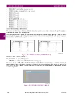
DEFAULT LABELS FOR LED PANEL 2:
The default labels are intended to represent:
•
GROUP 1...6
: The illuminated GROUP is the active settings group.
The relay is shipped with the default label for the LED panel 2. The LEDs, however, are not pre-programmed. To match the
pre-printed label, the LED settings must be entered as shown in the
User-programmable LEDs
section of chapter 5. The
LEDs are fully user-programmable. The default labels can be replaced by user-printed labels for both panels as explained
in the following section.
Figure 4–20: LED PANEL 2 (DEFAULT LABELS)
USER-PROGRAMMABLE LEDS
USER-PROGRAMMABLE LEDS
842782A1.CDR
SETTINGS IN USE
842783A1.CDR
Summary of Contents for B90
Page 10: ...x B90 Low Impedance Bus Differential System GE Multilin TABLE OF CONTENTS ...
Page 284: ...5 166 B90 Low Impedance Bus Differential System GE Multilin 5 8 TESTING 5 SETTINGS 5 ...
Page 334: ...10 8 B90 Low Impedance Bus Differential System GE Multilin 10 2 BATTERIES 10 MAINTENANCE 10 ...
Page 338: ...A 4 B90 Low Impedance Bus Differential System GE Multilin A 1 PARAMETER LISTS APPENDIX A A ...
Page 460: ...C 30 B90 Low Impedance Bus Differential System GE Multilin C 7 LOGICAL NODES APPENDIX C C ...
Page 476: ...E 10 B90 Low Impedance Bus Differential System GE Multilin E 1 IEC 60870 5 104 APPENDIX E E ...
Page 502: ...viii B90 Low Impedance Bus Differential System GE Multilin INDEX ...