background image


4


GENERAL INFORMATION 


Thank you for purchasing this GDI Communications LLC product. The XC300 is the 
perfect way to connect disparate Local Area Networks (LAN). There is no special wiring 
or special networking knowledge required. Using inexpensive, twisted copper pair wire 
the XC300 allows you to connect LANs that are separated by up to 4000ft, breaking the 
300ft Ethernet barrier. The XC300 provides reliable high-speed data communication in 
the harshest operating environments. It can operate in uncontrolled environments such 
as remote terminals or curb side distribution vaults. 
 
Designed to operate in the harshest environments the XC300 has an operating 
temperature range of -40°C to +65°C, in non-condensing humidity of up to 95%. It can 
be set up at altitudes of up to 10,000 feet. 
 
The XC300NT and XC300LT work together to create a transparent extension between 
two Ethernet LANs. POTS/ISDN calls can be made over the VDSL link without 
interfering with the data. 
 
This manual has been designed to enable you to install your XC300 extender by 
following the step-by-step installation procedure. Follow the step-by-step installation 
instructions outlined in Section titled - Installation. 

FEATURES 

  Easy to install standalone VDSL modems—no 

configuration required 

  Environmentally hardened for operation in harsh environments 

  Auto-sensing full or half-duplex Ethernet 

  Auto-sensing 10/100 operation 

  Extends network connections up to 4,000 ft (1,219 m) over 2-wire 24-AWG 

unconditioned lines 

  .7 to 26 Mbps symmetric and asymmetric line rate 

  Internal POTS/ISDN splitter on board 

 Transparent 

operation 

  LED indicators for Power, Ethernet Link & Activity, VDSL Sync 

  Surge suppression up to 20 kA  

  Available in rack-mount or standalone configurations 


Summary of Contents for XC300

Page 1: ...XC300 VDSL Network Extender Owners Manual ...

Page 2: ...ications LLC computer product or component thereof resulting from accident abuse or misapplication of the product and GDI Communications LLC assumes no liability as a consequence of such events under the terms of this Warranty GDI Communications LLC does not warrant the merchantability or fitness of this product for any particular purpose This limited warranty is in lieu of any and all other warra...

Page 3: ...E LAN ETHERNET INTERFACE 9 CONNECTING THE TELEPHONE POTS ISDN LINE 11 CONNECTING POWER 11 OPERATION 12 POWER UP 12 FRONT PANEL LED STATUS MONITORS 12 CUSTOMER SERVICE 14 SERVICE AND UNRESOLVED PROBLEMS 14 APPENDIX A 15 SPECIFICATIONS 15 APPENDIX B 17 FACTORY REPLACEMENT PARTS AND ACCESSORIES 17 APPENDIX C 18 INTERFACE PIN ASSIGNMENT 18 ...

Page 4: ...up to 10 000 feet The XC300NT and XC300LT work together to create a transparent extension between two Ethernet LANs POTS ISDN calls can be made over the VDSL link without interfering with the data This manual has been designed to enable you to install your XC300 extender by following the step by step installation procedure Follow the step by step installation instructions outlined in Section title...

Page 5: ...network Figure 1 shows a typical point to point application The XC300 is well suited to surveillance applications where cameras with digital output are placed in strategic locations to observe any activity within view of the camera The information from the camera can be transmitted to a central collection point up to 4000 ft away from the camera over inexpensive copper wire Having the ability to p...

Page 6: ... inefficient in this high noise environment The alternative is to use fiber optic cable that is expensive the end to end equipment is also expensive The XC300 is well suited for this environment Designed with robust VDSL technology the XC300 can deliver reliable high speed communications throughout the multi story building at a fraction of the cost of the fiber optic solution 6 ...

Page 7: ...cting the VDSL Line Interface on page 8 See Figure 4 for the rear panel connector arrangements 2 Connecting the Ethernet interface refer to section titled Connecting the LAN 10 100Base T Ethernet Interface on page 9 3 Connecting the POTS to a telephone or telephone line refer to the section titled Connecting the POTS ISDN line on page 11 4 Connecting the power plug refer to section titled Connecti...

Page 8: ...ust be an XC300NT and the other unit must be an XC300LT It does not matter which end is the XC300NT and which is the XC300LT The XC300LT always initiates the link As long as the XC300NT is powered on the XC300LT can establish a link by being powered ON or by a power reset To function properly the units must be connected together using twisted pair unconditioned metal wire between 19 0 9mm and 26 A...

Page 9: ...ion XC300NT LAN 10 100BaseT TX RJ45 Connector Pin out RX data input to XC300 RX data input to XC300 TX data output from XC300 No Connection No Connection TX data output from XC300 No Connection No Connection XC300LT LAN 10 100BaseT TX RJ45 Connector Pin out Connecting the LAN 10 100BaseT TX Ethernet Port to a Hub The XC300NT 10 100BaseT TX interface is configured as DTE Data Terminal Equipment jus...

Page 10: ...100BaseT TX Ethernet Port to a PC DTE The XC300 LAN 10 100Base T interface is configured as DTE Data Terminal Equipment If you wish to connect the XC300 to another DTE device such as network interface card NIC in a PC or XC300 in a back to back arrangement you must use a crossover cable as shown in Figure 9 XC300LT LAN 10 100BaseT TX Port 10 100BaseT TX Figure 9 10 100BaseT TX crossover cable NOTE...

Page 11: ... shown in Figure 10 Figure 10 XC300 PHONE RJ 11 POTS ISDN interface CONNECTING POWER An external AC cube style power supply is available Power to the XC300 is connected using the barrel jack on the rear panel No configuration is necessary for the power supply DC power supplied must meet the following requirements DC power must be regulated 5VDC 5 1 0A minimum Center pin is 5V The barrel type plug ...

Page 12: ...e XC300 please review section titled Connecting Power to verify that the unit is connected to the appropriate power source FRONT PANEL LED STATUS MONITORS The XC300 features four front panel LEDs that monitor power the Ethernet signals and the VDSL Connection Figure 11 shows the front panel location of each LED Table 1 describes the LED functions XC300 Figure 11 XC300 Front Panel LED location 12 ...

Page 13: ...at the end to end VDSL link between the XC300 set is established The VDSL LED is OFF when the link is down Ethernet Good Link Active Green Solid Green indicates that Ethernet link has been established Ethernet Activity Active Yellow Flashes to indicate Ethernet activity on the 10 100Base T Ethernet port Table 1 Front Panel LED Description ...

Page 14: ...any name mailing address telephone number RMA number and any special instructions During the first year after the date of purchase all labor and materials will be provided without charge There shall be no warranty for either parts or labor after the expiration of one year from the date of purchase or if in GDI Communications LLC s sole discretion the product has been deemed to be modified or abuse...

Page 15: ...ric or asymmetric DISTANCE Up to 4 000 ft 1 219 m LED INDICATORS Power Green VDSL Sync Green Ethernet Good Link Green Ethernet Activity Yellow POWER SUPPLY External AC power cube 90 to 240 VAC 47 to 63Hz 2 Watt OPERATING ENVIRONMENT TEMPERATURE RANGE 40 C to 65 C HUMIDITY Up to 95 non condensing DIMENSIONS 1 5H x 3 8W x 5 0D in 3 8H x 9 6W x 12 6D cm MOUNTING Metal enclosure with wallmount tabs Ru...

Page 16: ... with the manufacturer s instructions it may cause interference to radio and television reception The XC300 has been tested and found to comply with Class A computing device in accordance with specifications in Subpart B of Part 15 of FCC rules However there is no guarantee that interference will not occur in a particular installation ...

Page 17: ...SORIES GDI Communications LLC Model Description Model Description XC300LT VDSL Modem voice data XC300NT VDSL Modem voice data XC300 VDSL MODEM SET Kit includes one XC300LT and one XC300NT voice data NTPS 90 240VAC 5V reg DC 1A Universal Input Adapter ...

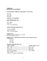
Page 18: ...TP VDSL LINE INTERFACE RJ 11 PHONE POTS ISDN INTERFACE RJ 11 POWER JACK Center pin regulated 5VDC 5 1 0A minimum Outer ring Common or Ground CONSOLE PLUG FRONT PANEL ACCESS for models equipped with front panel access Pin 1 VCC Pin 2 TX Pin 3 RX Pin 4 GND CONSOLE CABLE WITH DB 9 PLUG 18 ...

Page 19: ...19 Copyright 2003 GDI Communications LLC All Rights Reserved ...

Reviews: