background image

- 110 - 


          232001280G(13)


7.2 Maintaining the Worktable and Motion System 


7.2.1 Accessing the Worktable and Motion System 


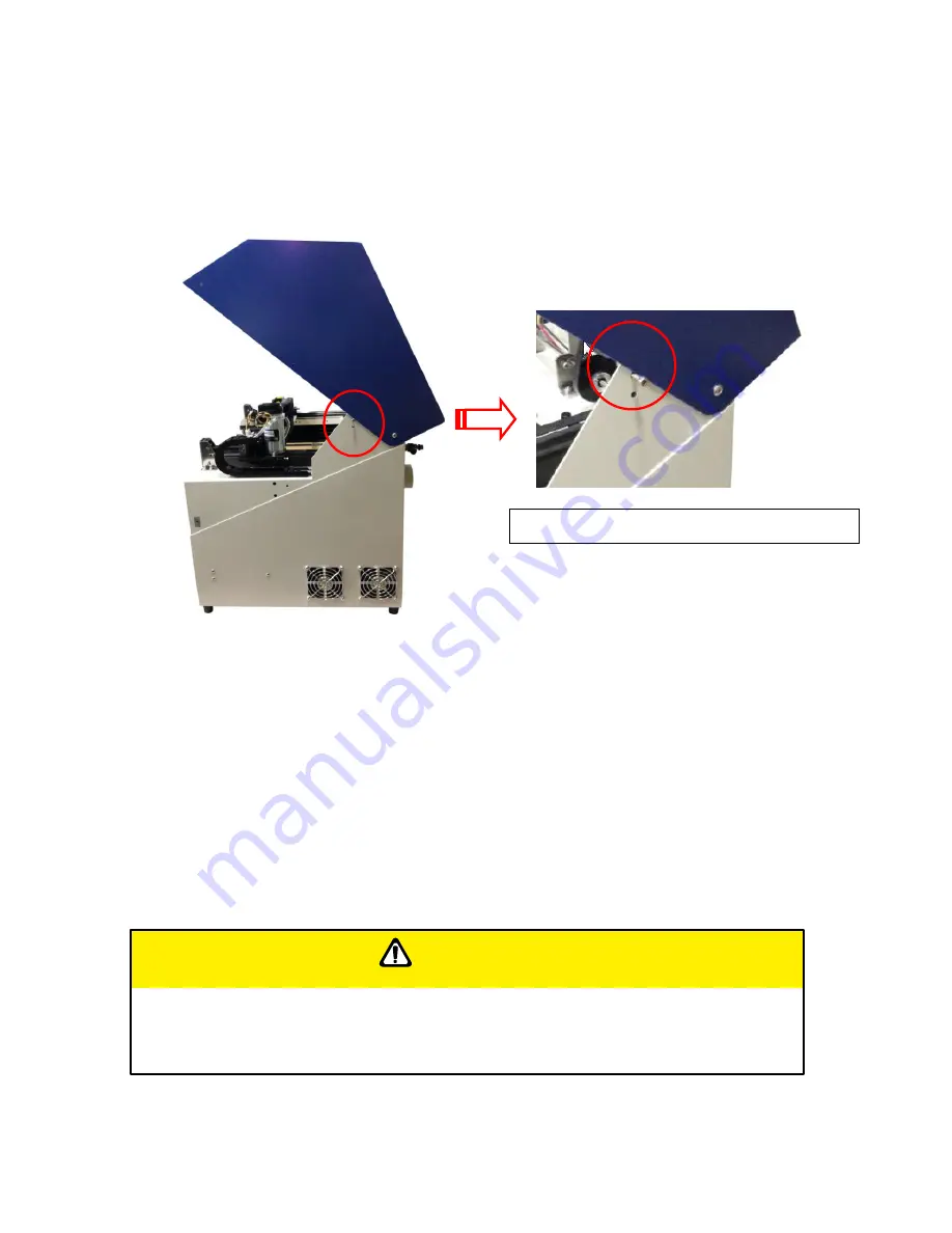
Remove the screws of the top chassis of the machine and lift the top off. 


 7.2.2 Cleaning the Worktable and Motion System 

 
7.2.2.1 Cleaning the Worktable and Motion System


Clean the working table and the motion system on weekly basis through the following steps: 

1)  Turn the power off and unplug the laser machine before cleaning. 

2)  Use a vacuum cleaner with a flexible nozzle to remove dust and debris from the worktable 

and motion system. 

3)  Apply small amounts of all-purpose cleaner, alcohol, or acetone to a paper or cotton towel to 

clean the working table. 

4)  Apply a soap solution, all-purpose cleaner, or alcohol to a paper or cotton towel to wipe dow 

the rails of the motion system. 

5)  Wait for all cleaning residue to dry completely before plugging in and operating the VENUS. 


CAUTION


•   Never pour or spray alcohol or acetone directly to the working table. 


•   Oil, alcohol and acetone can cause fires or smoke build-up if improperly used. 


Utilize the screws to hold the top cover 

Summary of Contents for LaserPro Venus II

Page 1: ......

Page 2: ...Pro VENUS is clearly on the cutting edge of all laser systems GCC understands that a creative technical background is the key to successful growth in the ever changing information economy We have a strong team of R D experts who propel our company to new heights From product development to manufacturing our engineers are dedicated to innovation and quality Guiding our solid technical base is a wor...

Page 3: ...nstallation of the LaserPro Print Driver 29 3 2 3 Parallels Desktops for MAC OS Users 30 3 2 4 Using Adobe s AP with GCC LaserPro machine 36 3 2 5 Using Autodesk Inventor with GCC LaserPro machine 40 3 2 6 Using eCut Plug in with GCC Laser Machine 43 Chapter IV Operating the LaserPro VENUS 44 4 1 Using the Hardware 44 4 1 1 Adjusting the LCD Display Screen s Contrast Setting 44 4 1 2 Graphic Contr...

Page 4: ... Maintaining the Worktable and Motion System 110 7 2 1 Accessing the Worktable and Motion System 110 7 2 2 Cleaning the Worktable and Motion System 110 7 2 2 1 Cleaning the Worktable and Motion System 110 7 2 2 2 Lubrication of the X Y Rails 111 7 3 Cleaning the Optics System 111 7 3 1 Removing the Mirrors 111 7 3 2 Cleaning the Mirrors 114 7 3 3 Removing and Cleaning the Focal Lens 114 Chapter VI...

Page 5: ...lass 4 equipment and users must wear goggles to operate the machine 1 3 The Safety Interlock System The laser system is equipped with a safety interlock system utilizing magnetic sensors on the top and side access doors laser activation and door LED lights on the control panel The magnetic sensors will deactivate the laser when either door is opened At this time the door LED light found on the con...

Page 6: ...f with the specific labels and their locations on the machine Below is a list of all the safety labels and their locations on the machine Product Label This label is located at the right back side of machine All the product information such as Serial Number Model Numbers Laser Power and Electric power can be found here Before requiring any tech support always provide service person the information...

Page 7: ...he possible laser path When operators close to these paths should be careful of the possible injury while machine working Laser Path Danger label This label indicates the laser path Normally you can find this label inside of machine Please be very careful of this area when you do the maintenance Aperture warning stickers mirror This label indicates the laser path Normally you can find this label i...

Page 8: ...g Label is written all the necessary information to be aware of in every operation Door open warning labels Protection Window Label This label indicates the protection wavelength You can find this label in the lower right corner of window ...

Page 9: ... Connect the machine to a properly grounded power outlet Ensure the voltage of the power source is identical to the voltage of the machine Do not open the laser access panel when the machine is plugged in Do not attempt to modify or disassemble the laser module Do not attempt to remove or modify any component of the machine s laser interlock safety system Ensure the immediate work area of the mach...

Page 10: ...xceeding 70 or where the ambient temperature is near the dew point Avoid small enclosed areas with poor ventilation Avoid areas with high levels of noise and electrical noise Select a location that is large enough to accommodate the laser system an exhaust system a computer and a work or storage table Select a location in which the ambient temperature remains between 15 C and 30 C 60 F to 85 F Sel...

Page 11: ...ke some time to familiarize yourself with this section regarding the mechanical overview of the LaserPro VENUS 2 1 Front View 2 2 Rear View Power Switch Control Panel Top Door Laser Access Panel Exhaust Port Air Assist Valve Power Inlet USB Port Ethernet Port ...

Page 12: ...aller one will get smaller spot size thus detailed engraving result while the bigger lens with bigger spot size is good for cutting application Focal Lens Focal Lens Plate Color Manual Focus Gauge Color 1 5 Optional Purple Blue 2 0 Standard Blue Blue 2 5 Optional Gold Gold 4 0 Optional Red Red Laser Carriage Stamp Jig Slot ...

Page 13: ... 232001280G 13 Lens Carriage Assembly Manual Focus Gauge Holder Insert to the hole of the holder for manual focusing Mirror Lens 2 0 2 5 or 4 0 Slot position for Lens 1 5 only Auto Focus Manual Focus Gauge ...

Page 14: ...cord into the machine s power cable inlet located on the right side of machine 3 1 2 Adjusting the LCD Display Screen s Contrast Setting Depending on the lighting of your immediate work area you may need to adjust the contrast of LCD display screen You may increase or decrease the contrast via the contrast adjustment wheel found on the inside of the right shoulder You can access this area by openi...

Page 15: ...Connectivity Connect the Ethernet Cable in accessory to the Ethernet Port on the rear of the laser system Follow below instruction for Ethernet connectivity setup Seal Clamp 2 or 4 diameter Flexible hose Fume Ventilation System NOTE 1 Never leave laser system unattended during laser cutting engraving and marking process even with Ethernet or Wi Fi connection setup this requirement cannot be avoide...

Page 16: ... illustration Step 1 Connect LAN cable to the LAN port of GCC laser engravers and turn on machine Step 2 Navigate the control panel through F4 Function Machine Setting LAN Setup Wizard IP Address Step 3 Go to Windows Control Panel Hardware and Sound Printer and right click on VENUS printer to check printer properties Step 4 Go to Ports tab of VENUS printer properties and select Add Port and follow...

Page 17: ... 17 232001280G 13 ...

Page 18: ... 18 232001280G 13 ...

Page 19: ...o the LAN port of GCC laser engravers and turn on machine Step 2 Navigate the control panel through F4 Function Machine Setting LAN Setup Wizard DHCP OFF Step 3 Navigate the control panel through F4 Function Machine Setting LAN Setup Wizard IP Address Step 4 Enter 192 168 3 X X refers to 1 255 value which can t be the same value with IP address setting in PC or Notebook for IP and 255 255 255 0 fo...

Page 20: ...l Panel Network and Internet Network Connections of computer right click mouse on the connected internet device and choose Properties Step 6 Choose the Internet Protocol Version 4 TCP IPv4 and click Properties to open up the setting window ...

Page 21: ...01280G 13 Step 7 Enter the IP address and Subnet mask setting values and choose OK Note the IP address 192 168 3 X X value can be 1 255 while can t be the same number as machine control panel setting in step 4 ...

Page 22: ...l Device and Printers of computer and right click on the laser machine printer choose Printer Properties Step 9 Select Add Pot under Ports tab and follow the instruction to enter the TCP IP information in laser machine s control panel in step 4 ...

Page 23: ... 23 232001280G 13 ...

Page 24: ... 24 232001280G 13 ...

Page 25: ...he communication might still not be able to work at this time you can refer to below actions to have a basic troubleshooting with IT technician 1 Verify the IP addresses you are using to see if they are valid i Open command line mode in your windows system Press Windows key R the Run window will appear type CMD in the blank bar then press OK to open command line mode ...

Page 26: ...x x is the IP address you set on the laser machine ie 192 168 100 101 press Enter to run the Ping tool If the communication is OK between your PC and Laser machine you will see reply from the destination IP If the communication is not ok you will see Request timed out message from destination IP ...

Page 27: ...t symbol then press enter the TCP IP configurations of this PC Laptop will show as below Set those two IP addresses to the laser machine and the PC Laptop which you want to communicate with laser Test Ping again to see if you can get normal response from destination IP if the communication is normal now can get reply from destination IP we can be sure the IP addresses we set originally are invalid...

Page 28: ...orted Any software that can output to the LaserPro Print Driver should work 3 2 1 Recommended Computer Configuration The LaserPro VENUS operates under Windows operating systems and is designed to work on a computer that meets the following minimum requirements Computer CPU Pentium 90 or equivalent or greater RAM 32MB or higher HDD 1 2 GB Hard Drive or greater SVGA 15 Super VGA Monitor On Board Par...

Page 29: ...elect Replace Existing Driver and click Next to continue 8 This screen will prompt you to provide a printer name Simply type in VENUS and select Yes or No if you want to use this printer as the default printer and click Next to continue NOTE When working with the LaserPro VENUS Print Driver within your graphics software you will need to have the VENUS set as the default printer to get proper outpu...

Page 30: ...ines by purchasing the Parallels Desktop software which allows you to install Windows OS in MAC computers and run Windows based software under MAC computer and output with GCC print driver 1 Purchase Parallels Desktops on its official website 2 Install Parallels Desktops under Mac OS environment ...

Page 31: ... 31 232001280G 13 3 Read Software License Agreement and press Accept to continue installation 4 Enter your Mac OS X User Name and Password then press OK ...

Page 32: ... 32 232001280G 13 5 Press Active 6 Press OK when activation is complete 7 Register Parallels Desktop ...

Page 33: ...Register and OK to complete the installation of Parallels Desktop 9 Open Parallels Desktop in the Applications folder then choose File New 10 Press Install Windows from DVD or image file then press continue to install windows OS ...

Page 34: ... 34 232001280G 13 11 Select CD ROM drive with the Windows installation CD 12 Enter the Windows OS product key 13 Select how you would like to run your Windows program ...

Page 35: ...installation procedure will start automatically 15 Windows OS installation is complete then you can refer to 4 2 5 Installation of the LaserPro Print Driver to install GCC LaserPro Print Driver 16 Install the AP that you want to use after the above installation is complete ...

Page 36: ...g Features users should firstly deselect Enable Advance Printing Features otherwise the machine is unable to recognize or read general files when uploaded Deselect Enable Advance Printing Features 1 Click to select Control Panel Devices and Printers 2 Select your printer for example Spirit right click your mouse and choose Properties to enter Spirit Properties setup ...

Page 37: ... 37 232001280G 13 3 The click the Advanced tab then deselect Enable Advanced Printing Features now all files can be recognized and uploaded ...

Page 38: ...001280G 13 File Transfer 1 Select your working object and then at the upper toolbar please choose File Print 2 At the print setup screen at Print Preset please select Custom and choose your printer e g Spirit ...

Page 39: ... 39 232001280G 13 3 Then click on the lower left tab of Setup to enter Preferences settings 4 After all preferences are set click Print to send file to the machine for print out ...

Page 40: ... 40 232001280G 13 3 2 5 Using Autodesk Inventor with GCC LaserPro machine 1 Start drawing 2 Delete border and title block by right clicking on sheet1 and selecting delete ...

Page 41: ...king area can be found on the paper tab of the windows driver 4 Start sketch 5 Engraving a Finish sketch b Right click on sketch and select properties c Line Type By Layer d Line Weight By Layer e Set color to match one of the 16 colors available in the pen tab of the windows driver ...

Page 42: ...280G 13 6 Cutting a Finish sketch b Right click on sketch and select properties c Line Type Continuous d Line Weight 001 in e Set color to match one of the 16 colors available in the pen tab of the windows driver ...

Page 43: ...Cut unique feature list Nesting Puzzles Material usage calculation AutoText to import files including image text QR code and barcode etc to the linked variable columns Slice Tile function CAD editing function Sign box and packaging box aided design 2D barcode QR code NOTE All objects created in one particular sketch will have the same properties meaning all will engrave or all will cut If you woul...

Page 44: ...ting Depending on the lighting of your immediate work area you may need to adjust the LCD display screen s contrast You may increase or decrease the display screen s contrast via the contrast adjustment wheel found on the inside of the front cover on the bottom right side You can access this area by opening the top window and looking inside to the near right side of the work area as shown in the p...

Page 45: ... any time any of the access doors are open and the laser LED is illuminated IMMEDIATELY unplugs the laser system and contact GCC technical support for service instructions DO NOT operates the laser system if any component of the safety system is malfunctioning DIRECTIONAL AND SELECTION BUTTONS Function F1 F2 F3 F4 Four function buttons allow you to select various functions which will change depend...

Page 46: ...ose jobs have been successfully loaded onto the system Delete Provides quick access to delete the current job Pause Pauses the current job process Press again to resume the current process Auto Focus After you have positioned your material and moved the laser carriage head to the area you want to work press this button and the system will automatically adjust the optimal vertical focal distance fo...

Page 47: ...t File Management Page Machine Information Page Main Work Page Select Lens Vector Mode Table Down Save Position Carriage Free LAN setup wizard Scaling Functions Page File Save Mode Tune auto focus Red Beam Command Mode Machine Setting Page Other Reset System File ...

Page 48: ... functions of the control panel This will be the page that is displayed when you are processing your jobs This page contains specific job information such as the current job s name Speed Power PPI DPI processing remaining times and jobs loaded Main Work Page Relevant Buttons Function F1 Prev Scroll through previous jobs F2 Next Scroll through next jobs F3 Z Go to Carriage Work Table Adjustment Pag...

Page 49: ...k Back to previous page F3 Down Manually decrease the height of the work table Z axis F4 Up Manually increase the height of the work table Z axis Directional Manually adjust the Y axis position of the laser carriage Directional Manually adjust the X axis position of the laser carriage Start Stop Back to Main Work Page Auto Focus Initiate the auto focus function Manual Focus Buttons Manually adjust...

Page 50: ...mmand Mode Save Position Flash Memory Set File Save Mode Set Vector Mode Tune Image Power Set Laser Wattage Set Fine Mode Other Reset Machine Information Page this page allows you to view information regarding the system such as the GCC logo machine name firmware version and other information Functions Page Relevant Buttons Function F1 Back Back to previous page F3 Help Display help F4 Recall Back...

Page 51: ...anagement Page Relevant Buttons Function F1 Back Back to previous page F2 Link Go to the Link DLink Page F3 D All Delete all loaded jobs F4 Del Delete the selected job Directional Scroll through your loaded jobs Enter Go to the File Information Page for the selected job Start Stop Go to the Main Work Page for the selected job Auto Focus Initiate the auto focus function Manual Focus Buttons Manuall...

Page 52: ...queue sequence The second column after the file name displays that job s next file in the job queue sequence First and last jobs in the job sequence you set will have a in the first and second columns respectively So according to the image above the job queue sequence has been set to be processed in this order 03 Marble cdr 01 Marble cdr 02 Marble cdr Link DLink Page Relevant Buttons Function F1 B...

Page 53: ...selected job File Information Page Relevant Buttons Function F1 Back Back to previous page F4 Edit Go to the File Management Edit Page for the selected job Start Stop Back to Main Work Page Auto Focus Initiate the auto focus function Manual Focus Buttons Manually adjust the height of the work table Z axis Main Work Page Press F4 Navigating to this page Functions Page Select File Management from th...

Page 54: ... to previous page Directional Scroll through the menu selections Directional Cycle through the available selections Enter Perform the selection Start Stop Back to Main Work Page Auto Focus Initiate the auto focus function Manual Focus Buttons Manually adjust the height of the work table Z axis Main Work Page Press F4 Navigating to this page Functions Page Select File Management from the menu File ...

Page 55: ...0 100 Vector Speed 0 0 100 Vector PPI 30 1524 Power Ramp YES NO File Edit Vector Page Relevant Buttons Function F1 Back Back to previous page F4 Save Save your current settings Directional Scroll through the menu selections Directional Adjust the value for that selection Start Stop Back to Main Work Page Auto Focus Initiate the auto focus function Manual Focus Buttons Manually adjust the height of...

Page 56: ...e Tune Image Power Set Laser Wattage Set Fine Mode Other Reset Machine Setting Page Relevant Buttons Function F1 Back Back to previous page Directional Scroll through the menu selections Enter Perform the selection Start Stop Back to Main Work Page Auto Focus Initiate the auto focus function Manual Focus Buttons Manually adjust the height of the work table Z axis Main Work Page Press F4 Navigating...

Page 57: ...g The LaserPro VENUS s default setting is 2 0 Lens 2 0 4 0 Set Lens Page Relevant Buttons Function F1 Back Back to previous page F4 Save Save your current settings Directional Cycle through selections Start Stop Back to Main Work Page Auto Focus Initiate the auto focus function Manual Focus Buttons Manually adjust the height of the work table Z axis Main Work Page Press F4 Navigating to this page ...

Page 58: ...Back Back to previous page F4 Save Save your current settings Directional Manually adjust the height of the work table Z axis Start Stop Back to Main Work Page Auto Focus Initiate the auto focus function Manual Focus Buttons Manually adjust the height of the work table Z axis Main Work Page Press F4 Navigating to this page Functions Page Select Machine Setting from the menu Machine Setting Page Se...

Page 59: ...en the LaserPro VENUS will not display this warning prompt at system startup Table Down YES NO Distance 0 165 mm Set Table Down Page Relevant Buttons Function F1 Back Back to previous page F4 Save Save your current settings Directional Scroll through the menu selections Directional Adjust the value for that selection Start Stop Back to Main Work Page Auto Focus Initiate the auto focus function Man...

Page 60: ...elevant Buttons Function F1 Back Back to previous page F4 Save Save your current settings Directional Cycle Red Beam between YES NO Start Stop Back to Main Work Page Auto Focus Initiate the auto focus function Manual Focus Buttons Manually adjust the height of the work table Z axis Main Work Page Press F4 Navigating to this page Functions Page Select Machine Setting from the menu Machine Setting P...

Page 61: ... system s default is Fine Vector mode sacrificing some speed for higher quality Modes Quality Production Speedy Slower speeds higher quality Faster speeds lower quality Set Vector Mode Page Relevant Buttons Function F1 Back Back to previous page F4 Save Save your current settings Directional Cycle Set Vector Mode between QUALITY VECTOR FINE VECTOR COARSE VECTOR SPEEDY VECTOR Start Stop Back to Mai...

Page 62: ...aller objects positioned away from the default start position top left of the work table Recall Position To recall the saved position simply go to Functions page and press F4 again to recall the saved position The laser carriage will be moved to the saved position Main Work Page Functions Page Navigating to this page press F4 Select Recall by pressing F4 Main Work Page Press F4 Navigating to this ...

Page 63: ...nt or positioning can only be done by the control panel Carriage Free YES NO Carriage Free Page Relevant Buttons Function F1 Back Back to previous page F4 Save Save your current settings Directional Cycle Carriage Free between YES NO Start Stop Back to Main Work Page Auto Focus Initiate the auto focus function Manual Focus Buttons Manually adjust the height of the work table Z axis Main Work Page ...

Page 64: ...utput formats are supported Mode Default HPGL Vector Pen 1 16 Vector Speed 0 0 100 Vector PPI 0 0 100 Power Ramp YES NO Set Command Mode Page Relevant Buttons Function F1 Back Back to previous page F4 Save Save your current settings Directional Scroll through the menu selections Directional Adjust the value for that selection Start Stop Back to Main Work Page Auto Focus Initiate the auto focus fun...

Page 65: ... the LaserPro VENUS even after each job has been processed File Save YES NO File Save Page Relevant Buttons Function F1 Back Back to previous page F4 Save Save your current settings Directional Cycle File Save between YES NO Start Stop Back to Main Work Page Auto Focus Initiate the auto focus function Manual Focus Buttons Manually adjust the height of the work table Z axis Main Work Page Press F4 ...

Page 66: ...ng page to scroll between different columns to enter the address and use Up or Down keys to change the numbers DHCP NO OFF Please refer to Chapter 4 1 3 for ethernet connectivity setup in Windows driver LAN Setup Wizard Page Relevant Buttons Function F1 Back Back to previous page F4 Save Save your current settings Directional Cycle DHCP between NO OFF or move between tabs on IP address settings Di...

Page 67: ...Back to previous page F4 Save Save your current settings Directional Adjust the X axis scaling numbers Directional Adjust the Y axis scaling numbers Start Stop Back to Main Work Page Auto Focus Initiate the auto focus function Manual Focus Buttons Manually adjust the height of the work table Z axis Main Work Page Press F4 Navigating to this page Functions Page Select Machine Setting from the menu ...

Page 68: ...ge ENGLISH others dependent on Firmware Unit METRIC ENGLISH EOF Alarm YES NO Air Delay 1 100 seconds TIP Depending on the material you are working with your laser settings and the desired results please experiment with the air delay to achieve your desired results Other Page Relevant Buttons Function F1 Back Back to previous page F4 Save Save your current settings Directional Scroll through the me...

Page 69: ...ck to previous page Directional Scroll through the menu selections Enter Perform the selection Start Stop Back to Main Work Page Auto Focus Initiate the auto focus function Manual Focus Buttons Manually adjust the height of the work table Z axis Main Work Page Press F4 Navigating to this page Functions Page Select Machine Setting from the menu Machine Setting Page Select Reset from the menu Reset ...

Page 70: ...on Machine Information Page Relevant Buttons Function F1 Back Back to previous page Directional Scroll through pages Start Stop Back to Main Work Page Auto Focus Initiate the auto focus function Manual Focus Buttons Manually adjust the height of the work table Z axis Main Work Page Press F4 Navigating to this page Functions Page Select Machine Information from the menu Machine Information Page ...

Page 71: ...t up LaserPro VENUS as the Printer 1 From the primary menu click FILE PRINT SETUP 2 From the navigation bar Name click VENUS OK 4 2 1 Page Setup and Orientation The first thing you must do before working with the LaserPro VENUS Print Driver will be to make sure the page and layout settings are properly configured within your graphics software You will need to access and edit the Page Setup or Layo...

Page 72: ...300 mm 11 8 inches and 210 mm 8 26 inches 7 Click OK to complete the paper size adjustment Tip Instead of manually selecting the Landscape and setting the Paper Width and Height you can simply click the Set From Printer function and CorelDraw will automatically set the proper orientation and dimensions based on LaserPro VENUS s work table VENUS must be set as the default printer prior to doing thi...

Page 73: ...raphics software CorelDraw is the designated graphics software used for this example For other graphics software you will need to access the corresponding Color Management page 1 From the primary menu click TOOLS COLOR MANAGEMENT and CorelDraw s Color Management will appear 2 Under the Style pull down menu select COLOR MANAGEMENT OFF 3 Click OK to complete the color management adjustments ...

Page 74: ...TIES The LaserPro VENUS Print Driver consists of seven primary sections pages in which you will be able to choose various cutting options and settings Option Page Pen Page Advance Page Paper Page Language Page Tip The following sections describe the specific functions for each of the settings found in the LaserPro VENUS Print Driver If you are new to laser cutting it is recommended that you first ...

Page 75: ...urself with the general principals of the laser process in Section 6 especially the Vector Cutting concepts This will make it easier to understand the various descriptions and terminology used in this section 4 2 3 1 LaserPro VENUS Print Driver Option Page Mode Setting OPTIONS PAGE DEFAULT SETTING Black White You can select from four primary mode settings depending on your application or results y...

Page 76: ...sted with the DPI setting found on the Options page Please note that selecting the Black White mode will add a new Raster page to the menu The Black White mode dithering settings can be changed from the Raster page Please refer to the Raster section below for details Experiment with different dithering settings to attain the desired results Tip The Black White mode interprets the processed image b...

Page 77: ...e 256 level gray scale image processing technology and 200 power level stamp steps production requirement to create slopes DPI Options Page DEFAULT SETTING 500 DPI dots per inch represents the number of times the laser will fire over a one inch path This setting determines the image resolution and quality when performing raster engraving functions Higher DPI settings result in cleaner and deeper e...

Page 78: ...is box will automatically engrave your image with a mirrored effect This setting will flip the image along the Y axis from left to right and vice versa Tip When engraving a stamp via the stamp mode the stamp image needs to be engraved in reverse mirrored for the final stamp to be correctly laid out Invert Options Page DEFAULT SETTING Unselected Checking this box automatically inverts reverses the ...

Page 79: ...nnecessary travel of the lens carriage at the expense of some quality SmartACT reduces the acceleration area to save of time to process a job Tip There is a greater performance gain when enabling SmartACT for designs that are vertically longer than they are horizontally wide as the SmartACT optimization modifies the movement of the X axis of the lens carriage Preview Options Page DEFAULT SETTING U...

Page 80: ... 80 232001280G 13 A filename will be prompted After entering the filename and pressing ok the Preview screen will be shown ...

Page 81: ...aved parameter setting files will be tagged with the Spi extension LOAD This function allows you to load those previously saved print driver parameters ORIGINAL This function will load the print driver s original factory parameter settings SAVE TO DEFAULT This function allows you to save your current print driver parameters as the default startup settings DELETE This function will delete the file ...

Page 82: ... 82 232001280G 13 ...

Page 83: ...tilize up to 16 different pens laser parameter settings make sure your graphics software can recognize and utilizes the 16 pen colors designated by the VENUS print driver If you would like to specify your own colors to designate to a particular laser setting then all you have to do is to double click on that particular pen color from the pen menu and a color manager window will open where you can ...

Page 84: ...aning higher speed setting for vectors lower pulse width and thus less cutting capability Not only speed setting affects actual processing time but also the job size complexity of the graphic and the position of the graphic in the working area Power Pen Page DEFAULT SETTING 50 The power slider controls the laser s power during operation engraving cutting power with a range setting from 0 100 The p...

Page 85: ...do kiss cutting it is recommended to set the PPI value to 400 and slower speed setting to keep curve and line with consistent cutting result no over burn in corner Raster Vector Pen Page DEFAULT SETTING Selected Checking the Raster checkbox will process only the raster functions for the areas of your design that correspond to that particular pen color Checking the Vector checkbox will process the ...

Page 86: ...e A general rule of thumb is for every 300 unit increment you will want to adjust the slider by 1 if the final output is 1 unit increment shorter or 1 if the final output is 1 unit increment longer than your graphic design setting Position Modes Advance Page DEFAULT SETTING Home These selections allow you to control the positioning of the laser head after each job completion and before the next su...

Page 87: ...ut a circle around the initial position of the laser head SmartCENTER The SmartCENTER function is a quick and easy way to precisely locate the center point between two points or four points Tip It is highly recommended you enable the red dot laser pointer when setting adjusting the Position Modes as this makes accurate positioning of your laser carriage for your particular jobs much easier Tip The...

Page 88: ... Extractionsystem it is recommended that you select the Bottom To Top image output direction option This will minimize the amount of dust byproducts lodged in the engraved sections as the Fume Extractionsystem is vented from the rear of the machine the same direction as the image is processed Border Advanced Page DEFAULT SETTING Unselected In cases where you are working with a negative image negat...

Page 89: ... and moving outwards If you try to process a vector image that has multiple layers without using this mode what may occur is the laser engraver may process the outer vector cutting first and any inner vector cutting will not be possible as your centerpiece material may have dropped to the cutting table This setting will always automatically direct the laser to cut from the inner most vector shape ...

Page 90: ...a for the unwanted parts and kiss cut half cut for the kept material parts after the laser cutting users can just peel off the materials to get rid of waste parts Visit GCC LaserPro Youtube channel for decal cutting introduction video at https www youtube com watch v YgGTMHqtWqE feature youtu be Enhanced Vector Mode Advance Page DEFAULT SETTING Unselected Decal layer No 2 Die cutting pen Cut throu...

Page 91: ...et distance value then the individual areas will be processed normally not via Cluster mode An example of an image that would benefit from the Cluster function would be 2 squares to be engraved side by side on the X axis with a 20 cm gap in between them In this scenario you would want to enable the Cluster setting and set the distance to a value less than 20 By doing so the laser will completely p...

Page 92: ... 92 232001280G 13 ...

Page 93: ...adjust the image tuning setting To adjust this setting we recommend that you engrave a small black square design as a sample and use a magnifying glass to view the engraved results When you look at your engraved test square under a magnifying glass you may notice the edges of your square may be slightly offset with every consecutive engraved even or odd line protruding past the square s ideal edge...

Page 94: ... small intricate text The following two pictures show engraved text magnified with no image tuning left picture and image tuning enabled right picture 4 2 3 4 VENUS Print Driver Language Page This page allows you specify the language displayed by the VENUS Print Driver Current language options allow for English Spanish French And Chinese Simplified Traditional Japanese and German Remember to selec...

Page 95: ... contrast levels of the engraved output Tip There are other ways to adjust an engraved image s contrast such as adjust the power speed settings or simply adjust the contrast of the image in software with the graphic software application Halftone Raster Page DEFAULT SETTING Dithering This option controls the way a raster engraved image is processed The digital image to engraved output process can b...

Page 96: ...he image is broken down into for the dithering process As an example selecting 2 x 2 will shade with a 5 grade halftone where as an 8 x 8 Dithering Matrix will dither with a 65 grade halftone The following diagram is an example of the raster effects when using the different dithering matrices Enhance Dithering DEFAULT SETTING Unselected Selecting this will produce a finer dithering output Error Di...

Page 97: ...e etc Please take some time to experiment with the multitude of raster options to get the one you feel is the best for your piece This is where much of the fun in engraving is experimentation 4 2 3 6 VENUS Print Driver Stamp Page Producing stamps require different operational steps than your standard engraving or cutting jobs The Stamp page offers dynamic options allowing you to customize your sta...

Page 98: ...roduce the stamp that is best suited for your application Adjustment Bar Power Level Stamp Page Another important aspect of creating a stamp is setting the slope level of the shoulder The shoulder is the section from the contact section of the stamp to its base This function allows you to adjust the slope for the shoulder sections of your stamp By sliding the sliders or directly input of power lev...

Page 99: ...hrough continuous firing of the laser to cut out various shapes When performing vector cutting operations imagine the laser head as a pair of scissors cutting out the lines specified in your design An example of a vector cut piece would be a customized dining mat as shown in the picture below The Spirit Series Print Driver determines which sections should be raster engraved or vector cut based on ...

Page 100: ...ers has been properly designated as an area to be vector cut Simply print your job output the file to the Spirit Series and watch as your string of characters is vector cut 5 3 Raster and Vector In some cases you will want to process both raster engraving and vector cutting tasks within a single project For example if you wanted to engrave a design onto a particular material and then cut a particu...

Page 101: ...graving Qulaity 1 Connect your digital camera to the computer by USB cable 2 Download the picture from the digital camera to the computer 3 Select the picture that you want to engrave 4 Import the image from the folder where the picture is located by selecting File Import ...

Page 102: ...32001280G 13 5 Convert the image to Bitmap by selecting the image and click on Bitmaps Convert to Bitmap 6 Change the Bitmap settings by setting Color to Grayscale 8 bit and Resolution to 300 dpi and click OK ...

Page 103: ... 103 232001280G 13 7 Finally Invert the image by selecting Effects Transform Invert ...

Page 104: ...is instruction is a simple example for general use There are many tips and tricks to achieve a good engraving quality It takes a lot of practice and experience to achieve a good engraving quality Different picture may need different modifications and different material may need different parameters ...

Page 105: ...utstanding features Each LaserPro Fume Extraction System is powered by a maintenance free continuous running turbine In order to ensure personnel safety and legal compliance the LaserPro Fume Extraction System is CE compliant for Europe To purchase a LaserPro Fume Extraction System contact your local authorized GCC distributor INSTALLATION Self Assembled Unit 1 Purchase an exhaust system at your l...

Page 106: ...ntially damaging moisture from the laser optics maximizing laser optic life In addition the air compressor provides the optimal air flow to the SmartAIR nozzles to minimize flaming suppress working temperatures and blow away dust and particle byproducts generated from the laser process Air Inlet Tubing Power Cord A Power Cord B Seal Clamp 2 Flexible hose Exhaust Ventilation System ...

Page 107: ...ube valve positioned towards the front side of VENUS As indicated below 5 Take the unattached end of the air tubing other end already connected to air compressor and connect it to the air tube connector on the air assist valve Make sure you press down on the air tube fastener when inserting the air tubing to form a tight secure attachment as indicated in the diagram below 2a 2b Plugs Plugs NOTE It...

Page 108: ... that the airflow regulator on the air assist valve is opened turn clockwise to increase the airflow counter clockwise to decrease the airflow The air nozzle under the laser head should emit a steady flow of air Air Flow Regulator Turn Clockwise to increase airflow Turn Counter Clockwise to decrease airflow Air Tube Fastener Air Tube Connector ...

Page 109: ...o not turn off and unplug the VENUS before cleaning Damage may occur to the system if you do not turn off and unplug the VENUS before cleaning Always turn off and unplug the VENUS before cleaning 7 1 Suggested Cleaning and Maintenance Supplies Cleaning Maintenance Tool Special notes Soap Solution or All Purpose Cleaner Paper Towels Cotton Cloth Denatured Alcohol DO NOT use alcohol on any painted s...

Page 110: ... 2 Use a vacuum cleaner with a flexible nozzle to remove dust and debris from the worktable and motion system 3 Apply small amounts of all purpose cleaner alcohol or acetone to a paper or cotton towel to clean the working table 4 Apply a soap solution all purpose cleaner or alcohol to a paper or cotton towel to wipe dow the rails of the motion system 5 Wait for all cleaning residue to dry complete...

Page 111: ...l and apply to the rails 7 3 Cleaning the Optics System 7 3 1 Removing the Mirrors We recommend you check the mirrors once or twice a week to see if they require cleaning If any debris or smoke residue is present use the following steps to clean them The following section will detail how to access and remove each of the four mirrors found on the LaserPro VENUS for cleaning Mirror 1 This mirror is ...

Page 112: ...ner 4 Re install the mirror after cleaning 5 Tighten the thumbscrew 6 Replace and secure the outer access panel Mirror 2 3 4 These mirrors are located in the worktable area of the LaserPro VENUS Mirror 3 Mirror 2 Mirror 4 Thumbscrew Thumbscrew Thumbscrew ...

Page 113: ...Clean the lens in the proper manner 3 Re install mirror 3 after cleaning 4 Tighten the thumbscrew Mirror 4 1 Unscrew the three thumbscrews front face of the laser head securing the laser carriage panel and remove the laser carriage panel to reveal mirror 4 and the focal lens 2 Loosen the top thumbscrew to remove mirror 4 as shown in the picture below 3 Clean the lens in the proper manner 4 Re inst...

Page 114: ...n the tissue covered mirror apply enough so that the tissue absorbs just enough to cover the mirror surface 4 Pull the tissue across the mirror in only one direction 5 Repeat the cleaning processes if the mirror is not completely clean after the first attempt 6 Make sure that the mirror is completely dry before reinstalling it CAUTION If the center of the mirror is scratched contact your LaserPro ...

Page 115: ... sides of the focal lens DO NOT apply any finger pressure or other cleaning solutions to the lens surface 4 After cleaning use a cotton swab to gently dry the focal lens and lens cover Tip Please clean the AutoFocus pin each time after completing the engraved job to make sure the AutoFocus pin is free to move ...

Page 116: ...he laser beam will not be generated when the top or front door is opened unless you short the connector of the magnetic switches 5 Check water level or temperature of water cooler for the machine If over heated laser beam will shut down automatically Other Problems Graphic Was Clipped Message The size or location of graphic image may be bigger or beyond legal working area Do not place graphic obje...

Page 117: ... can only be changed by replacing the chips or in the case of EEROM by special procedure PPI Pulses Per Inch PPI determines the gross amount of laser pulses there will be per linear inch PPI is exclusively for the vector setting A PPI setting of 500 results in the laser firing every 002 500 times per inch If the standard lens is producing a vector laser focal point of 007 then higher PPI settings ...

Page 118: ...ms MS Windows Computer Interface Full speed 2 0 USB 10 Base T Ethernet Display Panel 4 line LCD panel showing current file name total working time laser power engraving speed file s loaded into memory buffer setup and diagnostic menus Safety Class I Laser Product Compliant with EN60825 Class II Laser Product Compliant with CDRH Standard Feature Auto Focus V Red Dot Pointer V Down Vacuum Table V 3D...

Reviews:

Related manuals for LaserPro Venus II